Method and apparatus for repairing a pipe junction

Active Publication Date: 2013-09-26
LMK TECH LLC
View PDF6 Cites 20 Cited by
  • Summary
  • Abstract
  • Description
  • Claims
  • Application Information

AI Technical Summary

Benefits of technology

[0008]It is another object, feature, and/or advantage of the present invention to provide a seal at a junction of a pipe and another structure that prevents seal design failures by utilizing a mechanical anchor that travels at least partially through a pipe liner and the structure to be sealed. In some embodiments, at least a portion of the anchor is driven through the brim portion of a brim-style junction liner to ensure the integrity of the seal.
[0009]It is another object, feature, and/or advantage of the present invention to provide an improved method and apparatus for repairing the junction of a main and lateral pipe that utilizes compression gaskets to prevent leakage at the penetration points of the mechanical anchors.
[0010]It is another object, feature, and/or advantage of the present invention to provide an improved method and apparatus for repairing the junction of a main and lateral pipe that provides a compression seal to the majority of the area at the main and lateral junction.
[0011]These and/or other objects, features, and advantages of the present invention will be apparent to those skilled in the art. The present invention is not to be limited to or by these objects, features and advantages, and no single embodiment need exhibit

Problems solved by technology

However, there is nothing to ensure the structural integrity of the brim portion, as it only conforms to a portion of the main pipe interior proximal to the junction, relying on an adhesive bond with the host pipe to ensure the integrity of the seal.
There are no features in the currently available brim-style junction liner systems preventing the flange portion of the liner from detaching from the main pipe and breaching the seal created during the lining p

Method used


Image

  • Method and apparatus for repairing a pipe junction
  • Method and apparatus for repairing a pipe junction
  • Method and apparatus for repairing a pipe junction

Examples


Embodiment Construction

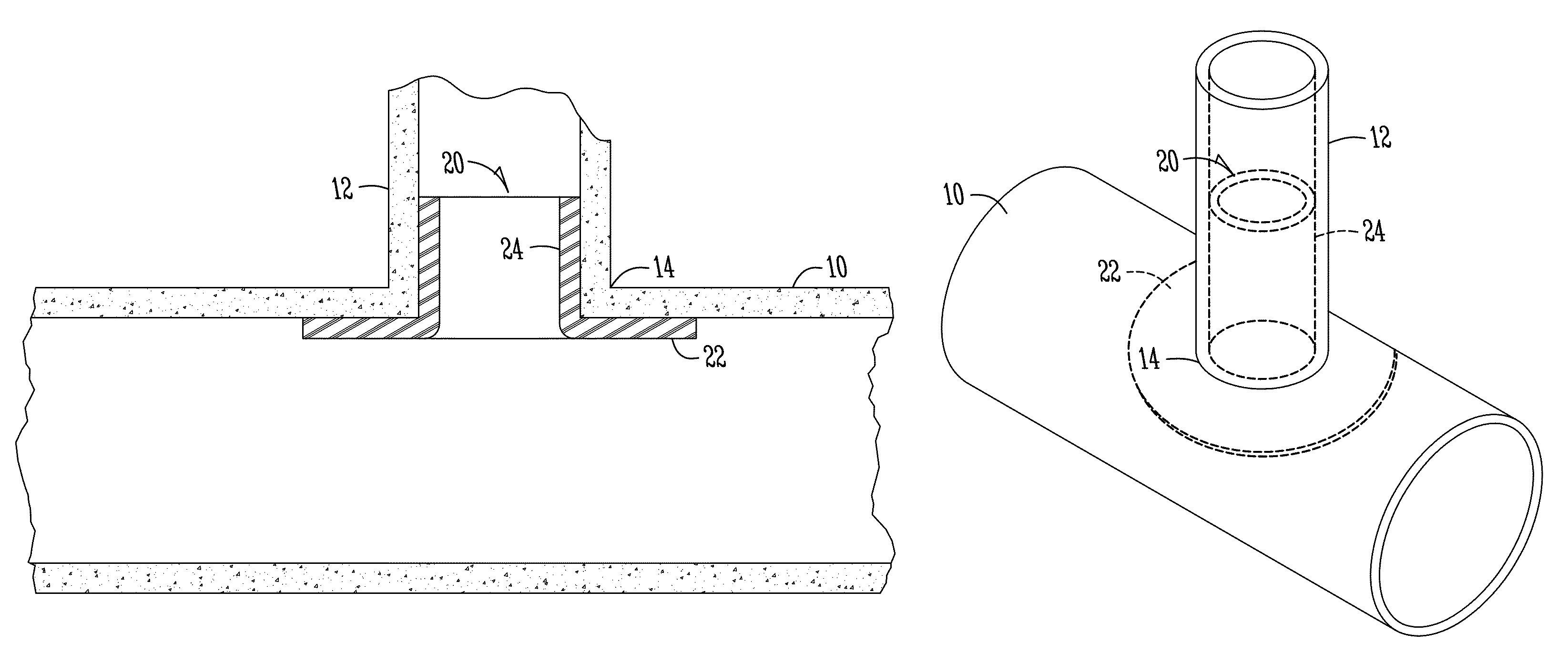
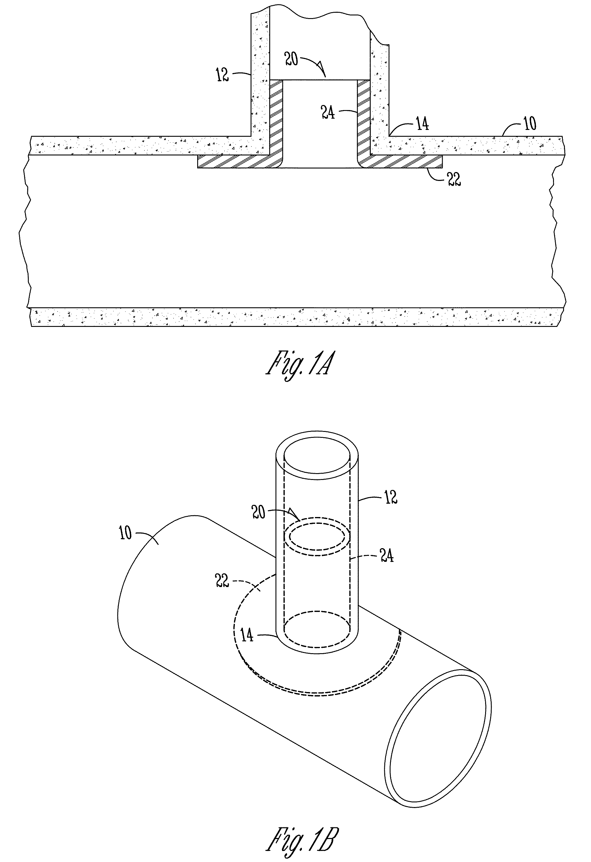
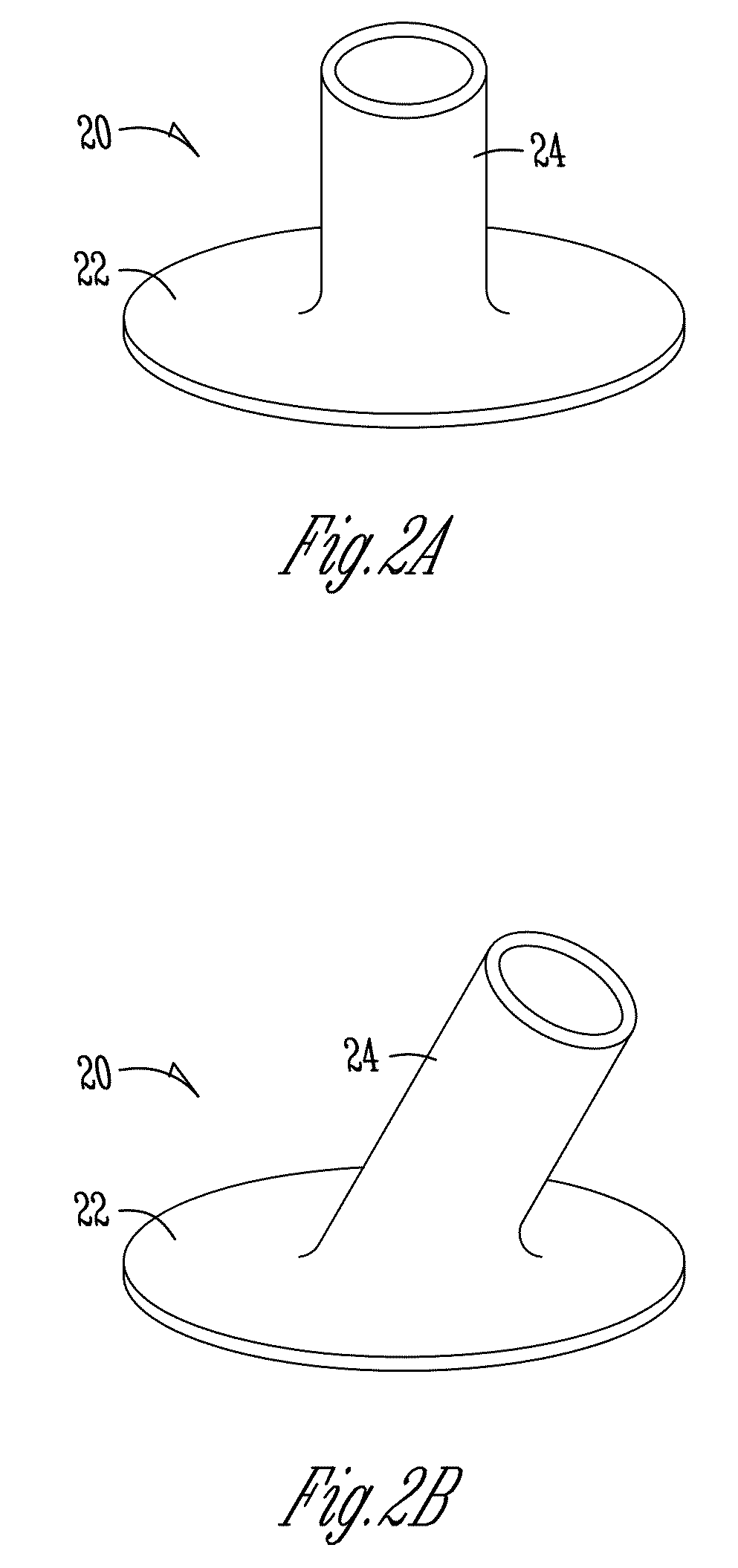
[0022]The present invention is directed towards an assembly and method for sealing a junction between tubes, passageways, conduits, or pipes. The invention includes providing a pipe liner having a tubular portion and a brim portion; placing the pipe liner against an interior wall of the pipe; placing the brim portion against the second structure; and securing the brim portion to the second structure using a mechanical anchor. The method may further include placing a compression gasket between the brim portion of the pipe liner and the second structure, and driving the mechanical anchor through the compression gasket and at least partially through the second structure.

[0023]The illustrated embodiments are described primarily in reference to junctions of sewer pipes. However, many other types of junctions are intended to be within the scope of this invention, including but not limited, to pipe / manhole junctions, gravity pipe junctions, pressure pipe junctions, water pipe junctions, an...


PUM

PropertyMeasurementUnit
Mechanical propertiesaaaaaaaaaa
Hydrophilicityaaaaaaaaaa
Compressibilityaaaaaaaaaa

Abstract

An assembly and method of sealing a junction of a pipe and a second structure are provided. The assembly includes a pipe liner having a tubular portion and a brim portion, and a mechanical anchor adapted to secure the brim portion of the pipe liner to the second structure. The assembly may further include a compression gasket for placement between the pipe liner and the pipe or second structure. The compression gasket may comprise a hydrophilic material, a hydrophobic material, or a compressible material. The methods of using the assembly include, but are not limited to, the use of a cured-in-place pipe liner.

Description

FIELD OF THE INVENTION[0001]The invention relates generally to a method and assembly for repair of junctions of tubes, passageways, conduits, or pipes. More particularly, but not exclusively, the invention relates to methods and devices for repairing a pipe junction with a mechanically-anchored pipe liner to create a fluid-tight seal at the junction.BACKGROUND OF THE INVENTION[0002]Many methods are currently known to rehabilitate or repair existing pipe junctions. For example, a cured-in-place pipe liner may be used to rehabilitate a pipe junction. Cured-in-place pipe liners are commonly used throughout the pipelining industry, and there are two common forms of cured-in-place pipe lining methods that have been used for the repair of the junction of a main and lateral sewer pipe. One cured-in-place system and method commonly used for the repair of such a junction is a brim-style junction liner, commonly referred to as a “top hat” system. This method of repairing a junction includes t...

Claims


Application Information

Patent Timeline
IPC IPC(8): F16L9/14B23P19/00
CPCY10T29/53F16L55/179Y10T137/0402
Inventor KIEST, JR., LARRY W.
Owner LMK TECH LLC
Why Eureka
Try Eureka