Theft Prevention Using Existing ABS Sensors

Inactive Publication Date: 2013-09-26
TEXAS INSTR INC
View PDF2 Cites 5 Cited by
  • Summary
  • Abstract
  • Description
  • Claims
  • Application Information

AI Technical Summary

Benefits of technology

[0005]A typical ABS system includes a number of wheel speed sensors that continually monitor the rotational speed of the wheels, and a control unit capable of applying and/or moderating the braking force applied to each wheel. By deter

Problems solved by technology

They range in complexity and function from very simple systems that simply detect that the car door was opened, to very complex ones employing an array of sensors that may include switches, pressure sensors, motion detectors, voltage monitors and acoustic sensors.
One of the more diff

Method used


Image

  • Theft Prevention Using Existing ABS Sensors
  • Theft Prevention Using Existing ABS Sensors
  • Theft Prevention Using Existing ABS Sensors

Examples


Example

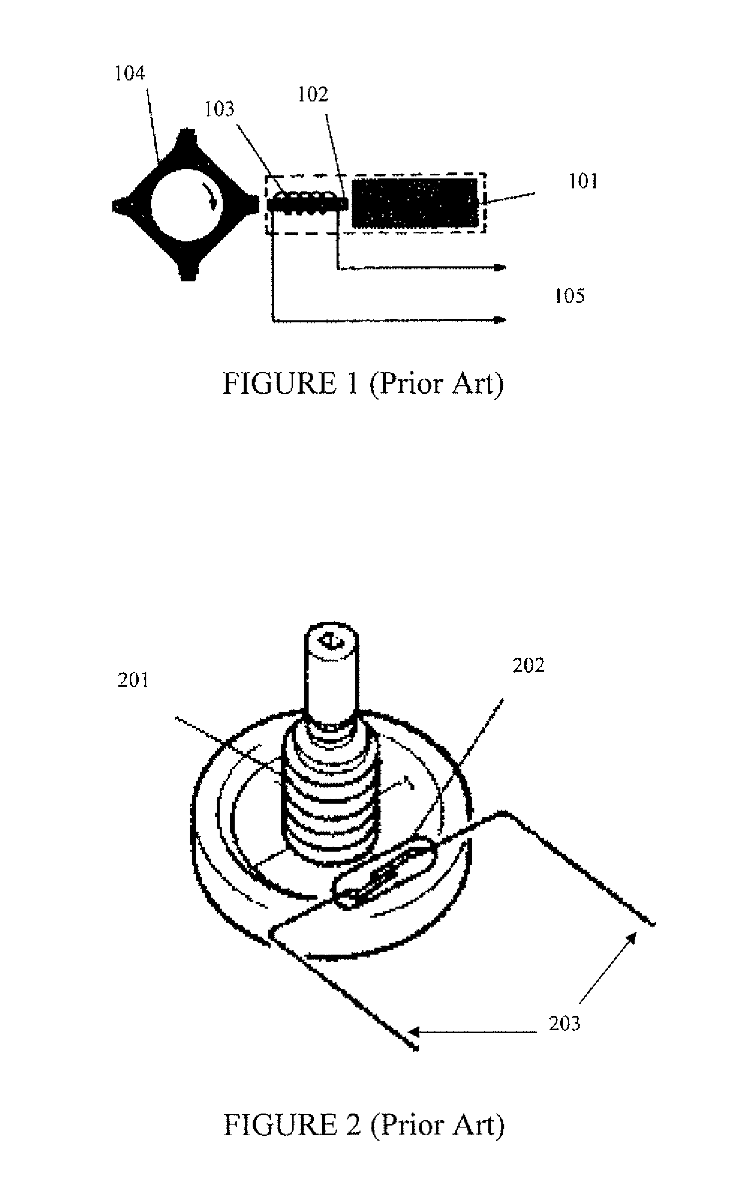
[0014]ABS systems may be implemented using a variety of sensors to detect and measure wheel movement. FIG. 1 shows a variable reluctance sensor where 101 is a permanent magnet in proximity to coil 102 wound on core 102. Rotor 104 is part of, or is attached to the wheel and has a number of lobes that pass in close proximity to coil 103 as the wheel rotates. Due to the change in magnetic field as the lobes pass the coil, a periodic voltage is generated in coil 103 whose frequency is representative of the wheel's rotational speed.

[0015]A simple magnetic reed switch may also be used to sense rotation. In FIG. 2 multi pole permanent magnet 202 is attached to the wheel, in close proximity to magnetic reed switch 202. Switch 202 will periodically open and close as the magnets pass by, thus alternately enabling and interrupting the current flow in connection 203. The rate of switch closure may be used to measure wheel rotation.

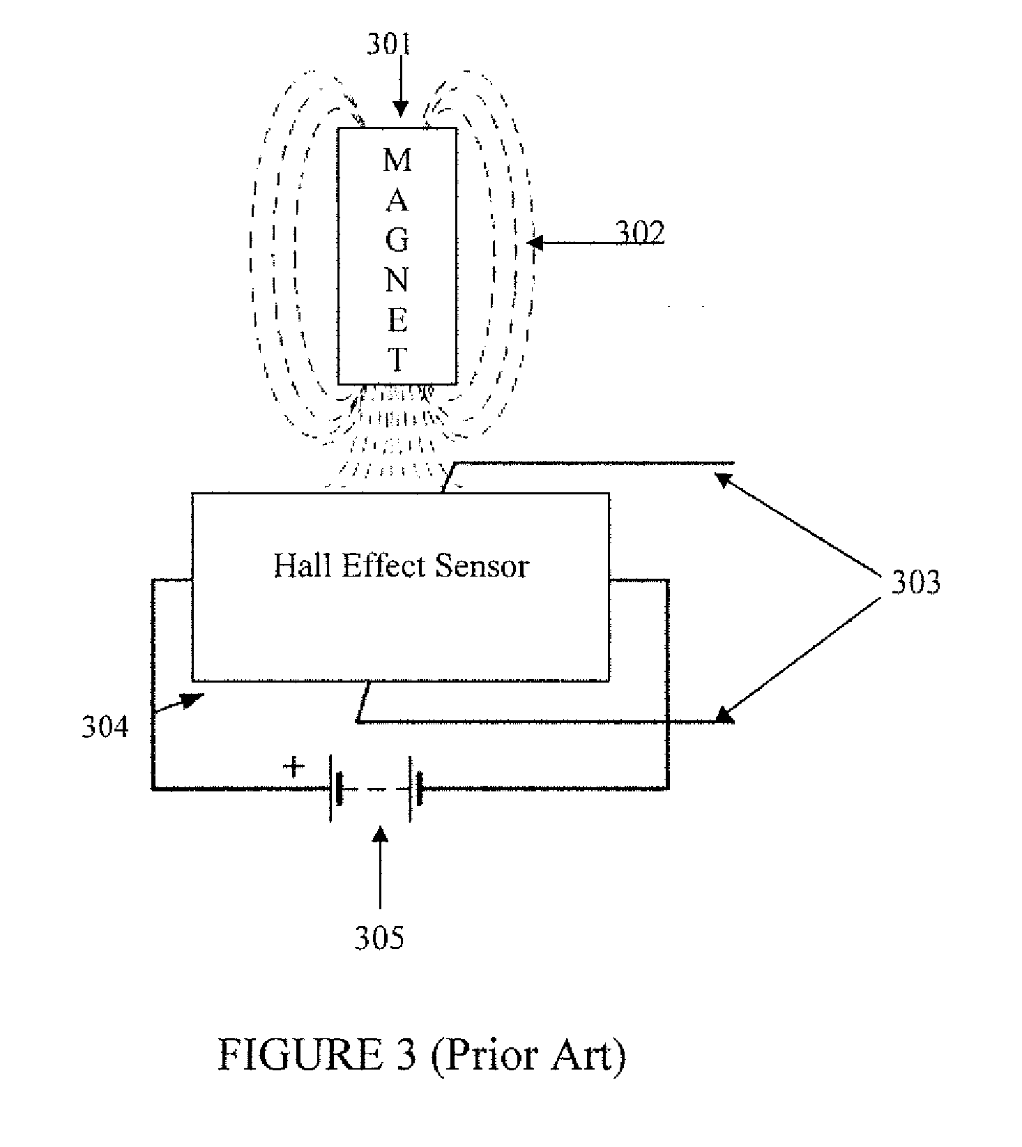
[0016]An alternate and very common sensor may also be constructe...


PUM


Abstract

The automobile theft prevention system proposed in this invention detects motion by using the existing wheel rotational sensors that are part of the anti lock braking and stability augmentation systems present in most automobiles, without the requirement of any additional hardware specific to the theft prevention system.

Description

TECHNICAL FIELD OF THE INVENTION[0001]The technical field of this invention is automobile security systems.BACKGROUND OF THE INVENTION[0002]A large number of theft prevention systems are available for automobiles. They range in complexity and function from very simple systems that simply detect that the car door was opened, to very complex ones employing an array of sensors that may include switches, pressure sensors, motion detectors, voltage monitors and acoustic sensors. They all have one parameter in common, the sensors are usually separate and distinct from the equipment normally available in the automobile.[0003]One of the more difficult events to detect in a reliable manner is movement of the automobile that may indicate towing or pushing. Most of the existing systems use a motion sensor of some kind that are either not sensitive enough to detect slow movement, or are prone to an excessive rate of false alarms. The invention described shows a reliable motion detection system ...

Claims


Application Information

Patent Timeline
IPC IPC(8): B60R25/10
CPCB60R25/08
Inventor COATES, KEVEN DALE
Owner TEXAS INSTR INC
Why Eureka
Try Eureka