Multilayer stack combinations with interleaved overlapping harmonics for wide visible-infrared coverage

a multi-layer stack and harmonic technology, applied in the field of multi-layer optical film constructions, can solve the problems of color issue often arises, and it is typically undesirable for the film to impart a significant colored (non-white) appearance to the display

Active Publication Date: 2013-09-26
3M INNOVATIVE PROPERTIES CO
View PDF2 Cites 51 Cited by
  • Summary
  • Abstract
  • Description
  • Claims
  • Application Information

AI Technical Summary

Benefits of technology

[0007]Recently, broadband polymeric multilayer optical films have been proposed that have intermediate amounts of reflectivity and transmission for light polarized parallel to at least one principal optic axis so that some significant amount of incident light is reflected, and another significant amount of the incident light (typically, the remainder of the incident light that is not reflected) is transmitted. Such films are referred to herein as partially reflecting multilayer optical films, or partially transmitting multilayer optical films. One approach to addressing color issues in such films is to provide them with only a single packet or stack of microlayers with a carefully tailored layer thickness profile, and to manufacture them without the use of any layer multiplier devices, to provide maximum control of the layer thickness profile and a corresponding minimum spectral variability in transmission or reflection over the visible wavelength range.

Problems solved by technology

The color issue often arises when the film is intended for use in a visual display system, e.g., where the film is a broadband reflective polarizer or a broadband mirror, and the display system is a liquid crystal display, luminaire, or backlight.
In such systems, it is typically undesirable for the film to impart a significant colored (non-white) appearance to the display, whether at normal incidence or for obliquely incident light.
In the case of coextruded polymeric multilayer optical films, such non-uniformities are typically the result of imperfect control of the layer thickness profile of the film relative to a target profile.

Method used


Image

  • Multilayer stack combinations with interleaved overlapping harmonics for wide visible-infrared coverage
  • Multilayer stack combinations with interleaved overlapping harmonics for wide visible-infrared coverage
  • Multilayer stack combinations with interleaved overlapping harmonics for wide visible-infrared coverage

Examples


example 1

Coextruded Polymeric Film Stack

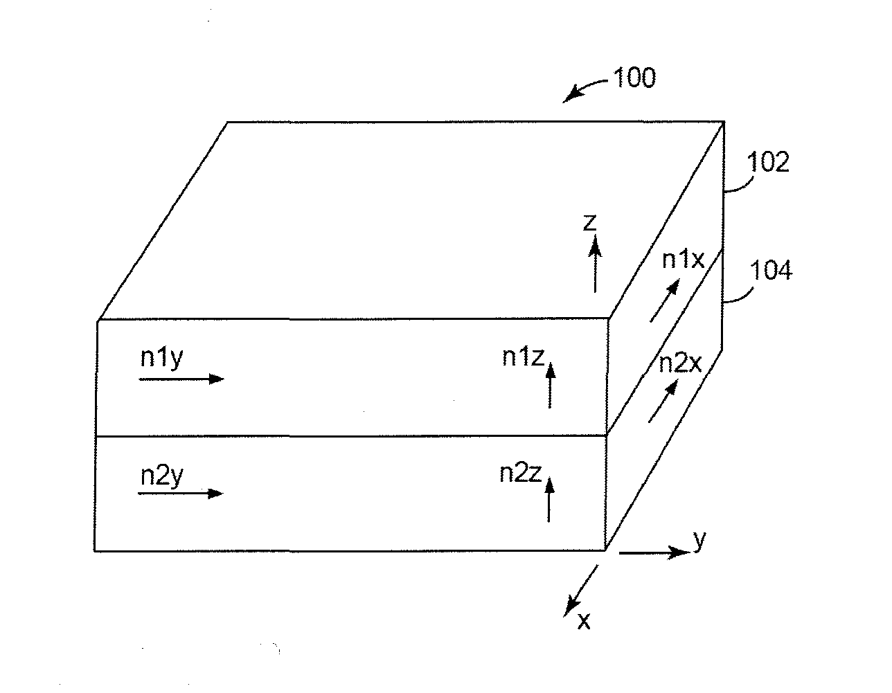
[0147]Two packets of 275 layers each of alternating low and high index polymer layers were coextruded as a cast web and then stretched in a tenter on a continuous film making line. The high index material was a 90 / 10 coPEN (90% naphthalate units to 10% teraphthalate units). For the design polarization, the birefringent high index material had a measured refractive index of 1.795. The low index material differed between packet 1 and packet 2 of the microlayers. The low index material for packet 1 was a 55 / 45 coPEN and having an isotropic index n=1.605. The low index material for packet 2 was NEOSTAR FN007 copolyester from Eastman Chemical and had a measured index of 1.505. All indices were measured at 633 nm.

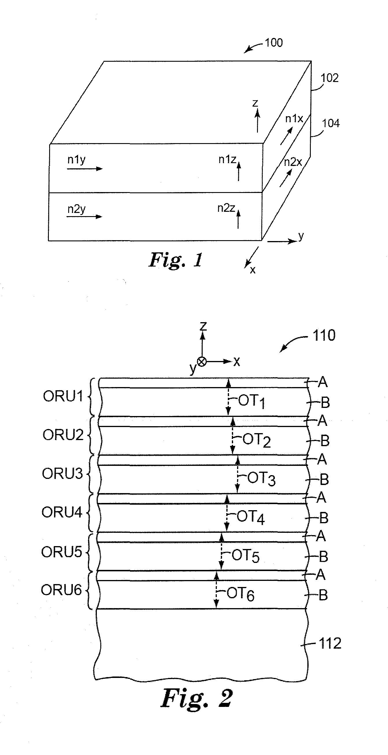
[0148]The layer thickness values of the oriented film were measured using Atomic Force Microscopy (AFM), and the layer thickness profiles 18a and 18b for packets 1 and 2 are shown in FIG. 18. When the layer thickness values are measured, the measure...

example 2

Coextruded Polymeric Film

[0164]Two packets of 375 layers each of alternating low and high index polymer layers were coextruded as a cast web and then stretched in a tenter on a continuous film making line. The high index material was PEN (poly(ethylene naphthalenedicarboxylate)). For the design polarization, the birefringent high index material had a measured refractive index of 1.845. The low index material was PETg (EASTAR GN071 copolyester from Eastman Chemical, Kingsport, Tenn.) with an index of 1.564. All indices were measured at 633 nm.

[0165]The process conditions for the fabrication of the film of Example 2 were chosen so as to generate an f-ratio of 0.64, for all of the ORUs, of both packet 1 and packet 2, and to provide a reflection band for a chosen linear polarization of light, that extends to about 1050 nm at normal incidence angle. The layer thickness values of the oriented film were measured using Atomic Force Microscopy (AFM). Measured reflection spectra for each of p...

example 3

Coextruded Polymeric Film

[0172]Two packets of 325 layers each of alternating low and high index polymer layers were coextruded as a cast web and then stretched in a tenter on a continuous film making line. The high index material was PEN (poly(ethylene naphthalenedicarboxylate)). For the design polarization, the birefringent high index material had a measured refractive index of 1.845. The low index material was PETg (EASTAR GN071 copolyester from Eastman Chemical, Kingsport, Tenn.) with an index of 1.564. All indices were measured at 633 nm.

[0173]The process conditions for the fabrication of the film of Example 2, were chosen so as to generate an f-ratio of 0.64, for all of the ORUs, of both packet 1 and packet 2, and to provide a reflection band for a chosen linear polarization of light, that extends to about 1250 nm at normal incidence angle. The layer thickness values of the oriented film were measured using Atomic Force Microscopy (AFM). Measured reflection spectra for each of ...


PUM


Abstract

A broadband mirror, polarizer, or other reflector includes separate stacks of microlayers. Microlayers in each stack are arranged into optical repeat units, and the stacks are arranged in series. At a design angle of incidence such as normal incidence, the second stack provides a second 1st order reflection band and a distinct second 2nd order reflection band with a second spectral pass band therebetween. The first stack provides a first 1st order reflection band that fills the second spectral pass band such that a single wide reflection band is formed that includes the first 1st order reflection band, the second 1st order reflection band, and the second 2nd order reflection band. In some cases, the single wide reflection band can include a first 2nd order reflection band of the first stack. In some cases, the first and second stacks may have apodized portions which monotonically deviate from respective baseline portions.

Description

CROSS REFERENCE TO RELATED APPLICATIONS[0001]This is a continuation-in-part application for patent under 35 U.S.C. §120 of pending international application PCT / US12 / 060,485, “Apodized Broadband Partial Reflectors Having Differing Optical Packets”, filed Oct. 17, 2012, which international application claims the benefit under 35 U.S.C. §119(e) of U.S. provisional application 61 / 549,614, filed Oct. 20, 2011, now expired. The international application and the provisional application are each incorporated herein by reference in their entireties.FIELD[0002]The present disclosure relates to, among other things, multilayer optical film constructions, with particular application to constructions in which distinct harmonic reflection bands from different optical stacks, including at least one 2nd order reflection band that is distinct from a 1st order reflection band, interleave and overlap (or substantially overlap) to provide a single wide reflection band that covers at least a portion of ...

Claims


Application Information

Patent Timeline
Patent Type & Authority Applications(United States)
IPC IPC(8): G02B5/30G02B5/28
CPCG02B5/281G02B5/285G02B5/3041G02B27/142G02B5/287G02B5/305G02B5/0841
Inventor KIVEL, EDWARD J.NEVITT, TIMOTHY J.WEBER, MICHAEL F.
Owner 3M INNOVATIVE PROPERTIES CO
Why Eureka
Try Eureka