Wiper motor

a technology of wiper motor and wiper blade, which is applied in the direction of cranks, vehicle cleaning, gearing, etc., can solve the problems of reducing the productivity or cost of the wiper motor, and achieve the effects of reducing the number of types of worm wheels, improving the productivity of the wiper motor, and facilitating mold replacement work

Active Publication Date: 2013-10-03
MITSUBA CORP
View PDF10 Cites 12 Cited by
  • Summary
  • Abstract
  • Description
  • Claims
  • Application Information

AI Technical Summary

Benefits of technology

[0014]According the present invention, since the first connecting holes and the second connecting holes are formed in the worm wheel, the worm wheel can be used in both cases that the output shaft is swung within the first swing range and that the output shaft is swung within the second swing range. Since the worm wheel can be commonly used in both cases that the output shaft is swung within the first swing range and that the output shaft is swung within the second swing range, it is not necessary to prepare different worm wheels for the both cases that the output shaft is swung within the first swing range and that the output shaft is swung within the second swing range, and thus, the number of types of worm wheels can be reduced. Therefore, it makes the control of parts of the worm wheel easy, and the mold replacement work easy by reducing the number of molds or inserts for molding the worm wheel and then, it can be possible to improve the productivity

Problems solved by technology

However, since the increase of the number of types of worm wheels increased, complicated parts control, complicated mold chan

Method used


Image

  • Wiper motor
  • Wiper motor
  • Wiper motor

Examples


Embodiment Construction

[0024]Hereinafter, embodiments of the present invention are described in detail on the basis of drawings.

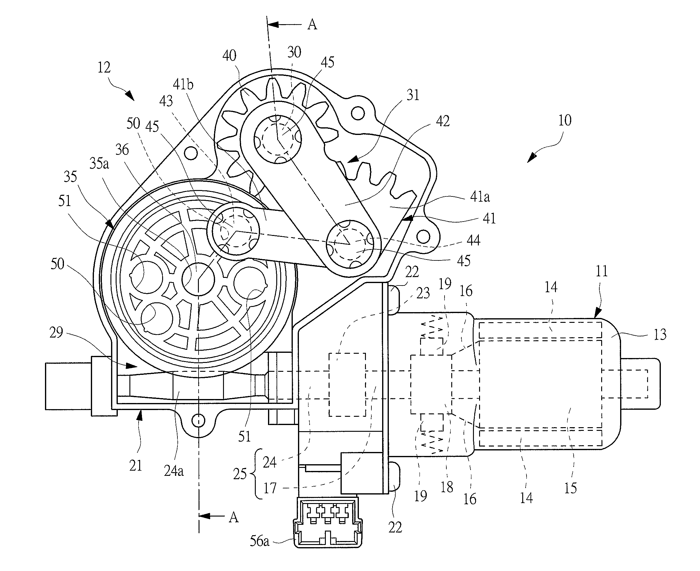
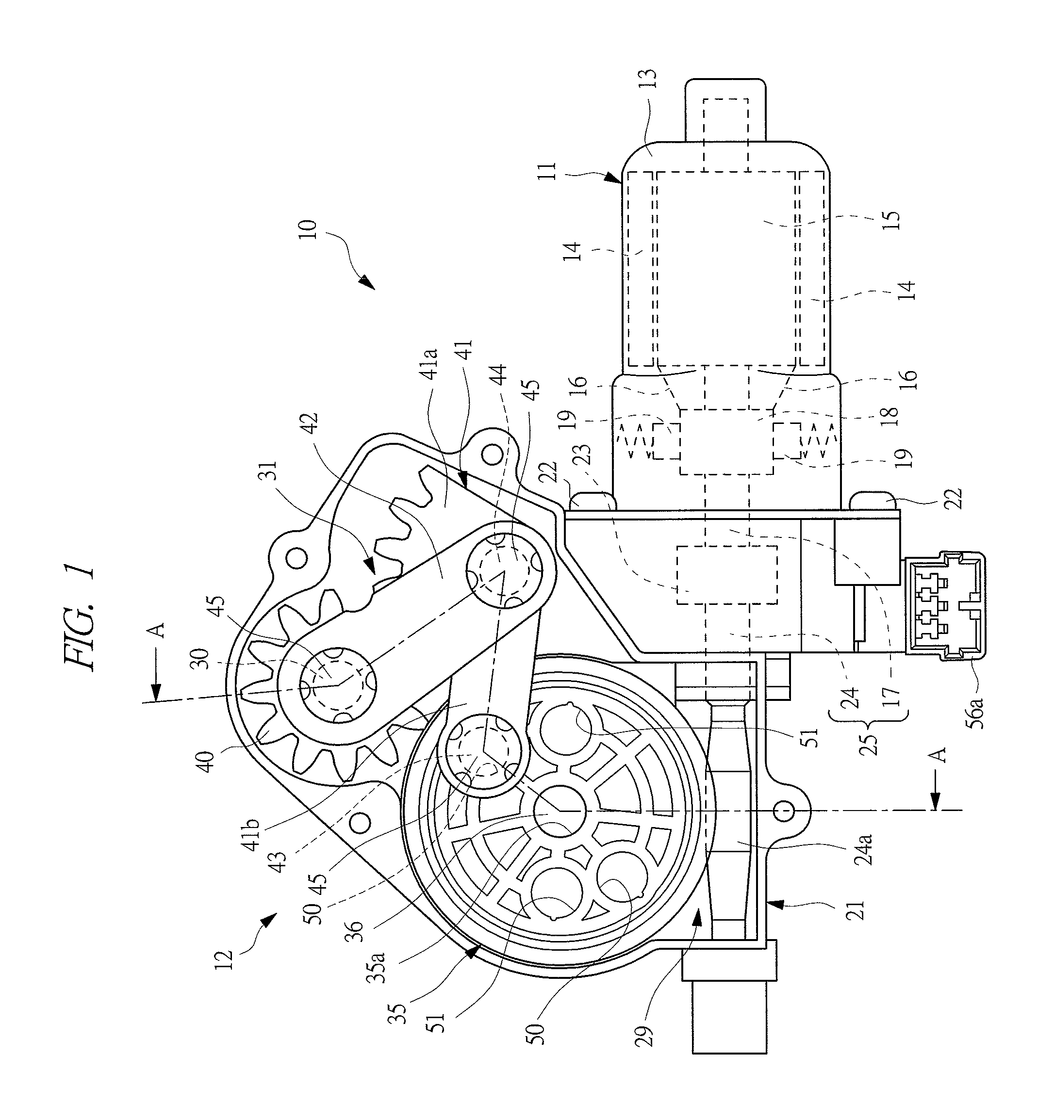
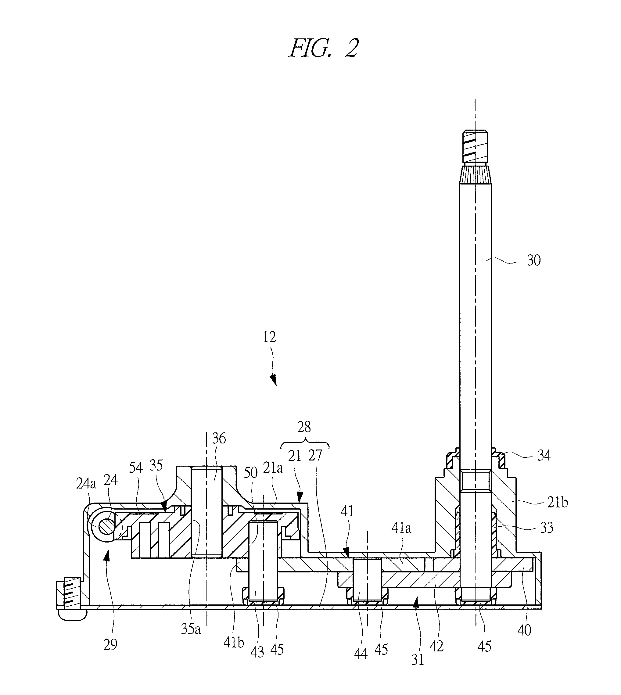
[0025]A wiper motor 10 shown in FIG. 1 is used as a drive source of a rear wiper device for wiping a rear window glass mounted on a vehicle such as an automobile. This wiper motor 10 has a motor body (electric motor) 11, and a gear unit portion 12 comprising a motion conversion mechanism converting turning motion of the motor body 11 into swinging motion and transmitting the swinging motion.

[0026]The motor body 11 is a brushed DC motor, and comprises a motor case (yoke) 13 formed by pressing a thin steel sheet or the like to a cylinder with a bottom. A plurality of arc-shape permanent magnets 14 magnetized to the N pole and the S pole in a radially inward direction respectively face each other and fastened to an inner periphery of motor case 13. An armature 15 facing each permanent magnet 14 via a micro space is rotatably contained inside motor case 13, and a plurality of coils 1...


PUM


Abstract

A wiper motor 10 has a reduction mechanism 29 for reducing the rotational speed of a motor shaft 25 and transmitting the reduced speed, and a motion conversion mechanism 31 for converting the rotational motion of the reduction mechanism 29 into a rotational motion and transmitting the motion to the output shaft 30. A pair of first connection holes 50 and a pair of second connection holes 51 are formed on a worm wheel 35 at a position deviated in a radial direction from an axial center of the worm wheel so that each of the holes is opened at the side of one axial end side. The worm wheel 35 can be used for both cases in which the output shaft 30 is swung within a first swinging region and in which the output shaft 30 is swung within a second swinging region.

Description

CROSS-REFERENCE TO RELATED APPLICATION[0001]This application is entitled to the benefit of and incorporates by reference essential subject matter disclosed in International Patent Application No. PCT / JP2011 / 077569 filed on Nov. 29, 2011 and Japanese Patent Application No. JP2010-276021 filed on Dec. 10, 2010.TECHNICAL FIELD OF THE INVENTION[0002]The present invention relates to a wiper motor for driving a wiper member mounted on an automobile and so on.BACKGROUND OF THE INVENTION[0003]As a drive source for driving a wiper member, a wiper motor is used in a rear wiper device for wiping a rear window glass mounted on a vehicle such as an automobile. The wiper motor has an electric motor such as a brushed motor. A speed reduction mechanism and a motion conversion mechanism are contained in a gear case mounted on the electric motor. The speed reduction mechanism comprises a worm rotated by the electric motor and a worm wheel meshing with the worm. The rotation of the electric motor is r...

Claims


Application Information

Patent Timeline
IPC IPC(8): F16H21/40
CPCB60S1/166B60S1/26Y10T74/18184F16H21/40B60S1/3495F16C3/28F16H21/42B60S1/08B60S1/185
Inventor TOKIZAKI, TEPPEIOTA, SHIGEKI
Owner MITSUBA CORP
Why Eureka
Try Eureka