Hybrid gas surface burner

a burner and surface technology, applied in the direction of gaseous heating fuel, stoves or ranges, combustion types, etc., can solve the problems of affecting the efficiency and performance of the burner, the maximum output is limited by the system gas flow handling capability, and the minimum output is limited, so as to achieve the effect of reducing the number of burners, and maintaining high rate performan

Inactive Publication Date: 2013-10-03
HAIER US APPLIANCE SOLUTIONS INC
View PDF10 Cites 21 Cited by
  • Summary
  • Abstract
  • Description
  • Claims
  • Application Information

AI Technical Summary

Benefits of technology

[0013]Advantageously, illustrative embodiments of the present invention provide improved multi-stage burners. The disclosed multi-stage burners can heat food more evenly when at substantially minimum settings while maintaining high rate performanc

Problems solved by technology

The maximum output is limited by system gas flow handling capabilities and safety considerations.
The minimum output is limited by the ability of the burner to maintain a stable flame under transient pressure fluctuations caused, for example, by air currents in the room, or sudden opening or closing of nearby cabinet doors or, if applicable, the oven door.
These techniques, however, impa

Method used


Image

  • Hybrid gas surface burner
  • Hybrid gas surface burner
  • Hybrid gas surface burner

Examples


first embodiment

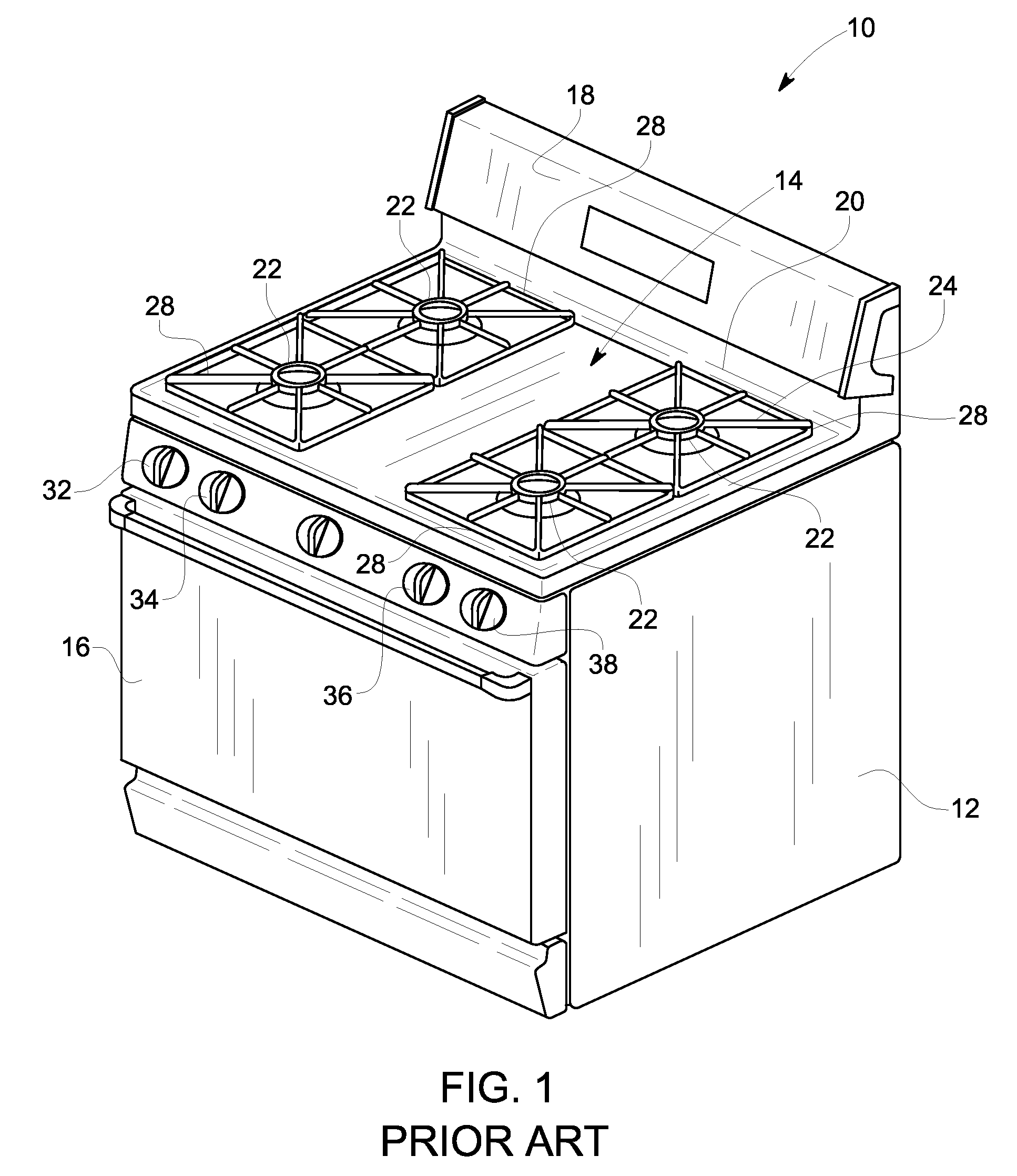
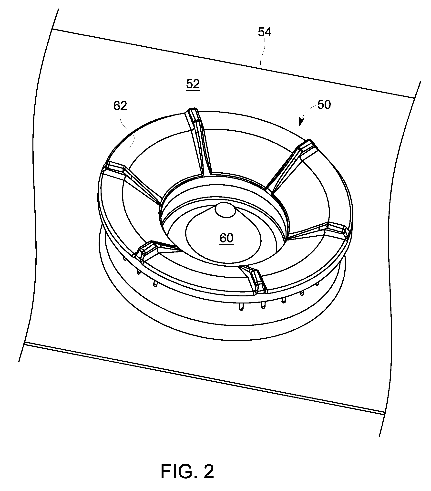
[0026]FIG. 2 is an exemplary burner assembly 50 applicable to gas range 10 shown in FIG. 1. Burner assembly 50 is mounted on a cooktop surface 52 of a cooktop 54, and includes an inner IR burner 60, and an outer gas burner 62 concentric with inner IR burner 60. A number of alternate embodiments of the inner IR burner 60 are discussed further below in conjunction with FIGS. 3 through 6. The particular embodiment of the burner assembly 50 shown in FIG. 2 corresponds to a first embodiment, the details of which are discussed further below in conjunction with FIG. 3. In the exemplary embodiment, cooktop 54 is fabricated from one of steel or glass. Alternatively, cooktop 54 is made of other suitable materials.

[0027]The exemplary gas surface burner 50 of FIG. 2 employs a hybrid approach to surface burners that seeks to take advantage of the benefits of both premixed and atmospheric partially premixed burners. As discussed further below, according to one aspect of the invention, the inner b...

exemplary embodiment 300

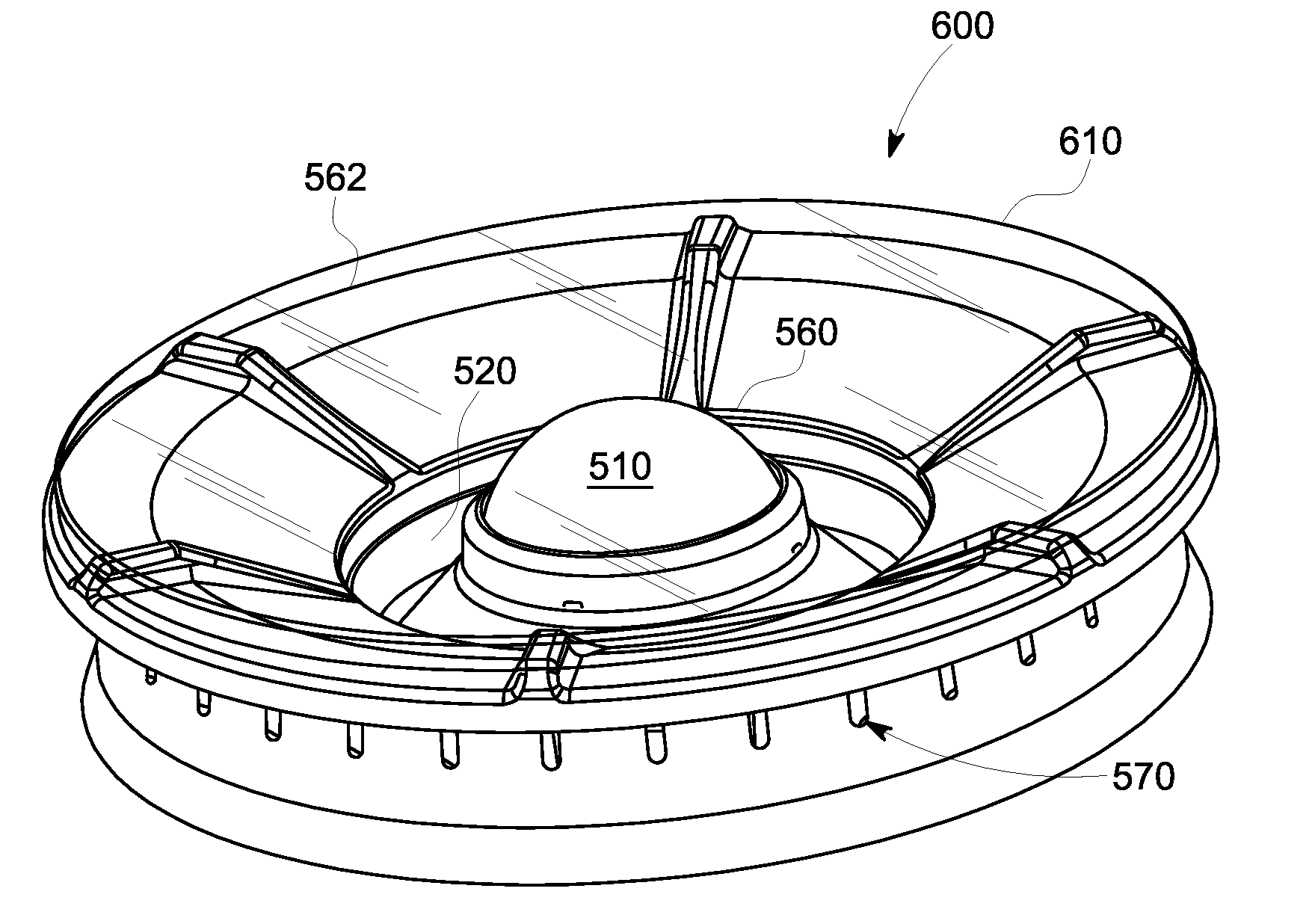
[0029]FIG. 3 illustrates a first exemplary embodiment 300 of the multi-ring burner assembly 50 of FIG. 2. In the exemplary burner assembly 300 of FIG. 3, the central simmer burner 360 is embodied as an annular IR ring 310 that emits IR energy inward towards a centrally located parabolic reflector 320. The exemplary annular IR ring 310 is substantially vertical, that is, it extends axially in a substantially vertical direction relative to the plane of the supporting surface, and can be fabricated, for example, using a stainless steel mesh. The parabolic reflector 320 can be fabricated, for example, using a ceramic material, stainless steel, or another high temperature alloy, such as Inconel™. The shape of the reflector 320 may be manipulated to control the heat flux to the cookware, as would be apparent to a person of ordinary skill in the art. The outer gas burner 362 includes a plurality of ports 370 to support traditional blue flames.

[0030]Among other benefits, an overhang 315 of ...


PUM


Abstract

A gas burner assembly is provided for a cooking appliance. The gas burner assembly comprises an outer gas burner configured to provide an outer cooking flame; and an inner infrared burner configured to provide an inner cooking flame. A gas cooking appliance is also provided that comprises a cooktop surface; and a gas burner assembly that comprises an outer gas burner configured to provide an outer cooking flame; and an inner infrared burner configured to provide an inner cooking flame.

Description

BACKGROUND OF THE INVENTION[0001]The subject matter disclosed herein relates to gas appliances, such as gas ranges, and more particularly, to multi-stage surface burners for use in such gas appliances.[0002]For gas burners that are used as surface heating units in cooking appliances, such as ranges and cooktops, a high turndown ratio is generally desirable. A turndown ratio is a ratio of maximum output to minimum output. For a given burner, the maximum output typically signifies the “power” or “speed” of the burner and the minimum output is related to the simmer capability of a burner. The maximum output is limited by system gas flow handling capabilities and safety considerations. The minimum output is limited by the ability of the burner to maintain a stable flame under transient pressure fluctuations caused, for example, by air currents in the room, or sudden opening or closing of nearby cabinet doors or, if applicable, the oven door.[0003]A number of techniques exist for improvi...

Claims


Application Information

Patent Timeline
IPC IPC(8): F24C3/08
CPCF24C3/08F24C3/085F23D14/06F23D14/145
Inventor CADIMA, PAUL BRYANHAN, BAI
Owner HAIER US APPLIANCE SOLUTIONS INC
Why Eureka
Try Eureka