Arc spring and damper apparatus

a technology of arc spring and damper, which is applied in the direction of fluid gearing, coupling, fluid gearing, etc., can solve the problems of fatigue breakdown likely to occur at the inner circumferential, non-uniform twist level of coil member produced by arc spring compression, and conventional arc springs are not configured to effectively absorb impact torque through the whole coil member, etc., to achieve the effect of large impact torque and large strok

Inactive Publication Date: 2013-10-03
AISIN AW INDUSTRIES CO LTD
View PDF3 Cites 12 Cited by
  • Summary
  • Abstract
  • Description
  • Claims
  • Application Information

AI Technical Summary

Benefits of technology

The present invention is designed to provide an arc spring and a damper system that reduces the stress on the coil member, allowing the arc spring to compress more and absorb larger amounts of impact torque.

Problems solved by technology

In the case of a curved arc spring, however, the torsion level of the coil member produced originating from the compression of the arc spring is nonuniform.
Hence, when the arc spring is repeatedly compressed, a fatigue breakdown is likely to occur at the inner circumferential portion of the arc spring rather than the outer circumferential portion of the arc spring.
That is, conventional arc springs are not configured to effectively absorb impact torque through the whole coil member.
As a result, the torsion stress of the coil member forming the inner circumferential portion of the arc spring is likely to exceed the tolerance.

Method used


Image

  • Arc spring and damper apparatus
  • Arc spring and damper apparatus
  • Arc spring and damper apparatus

Examples


Embodiment Construction

[0038]An explanation will now be given of an embodiment that substantiates an arc spring of the present invention and a damper apparatus thereof with reference to FIGS. 5A to 17.

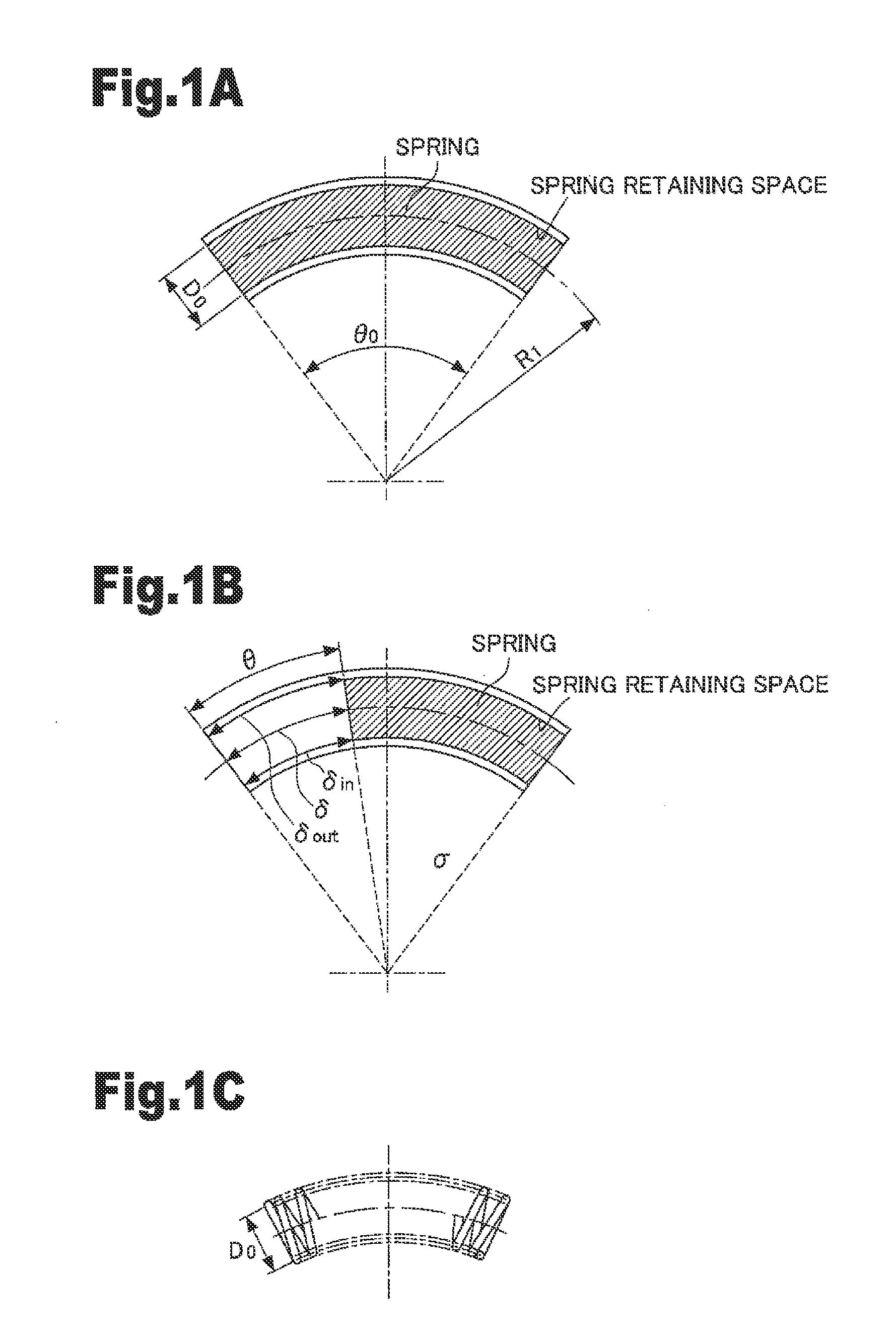
[0039]FIG. 5A illustrates an arc spring 1 in a free condition. FIG. 5B illustrates an arc spring 2 retained in a spring retaining space 3. As illustrated in FIG. 5A, the arc spring 1 has an average diameter D0, a reference radius Ra that is a predetermined curvature radius, and a free angle θa. Conversely, the spring retaining space 3 has a reference radius (attachment diameter) R1 that is a predetermined curvature radius and an attachment angle θ0. That is, the arc spring 1 has a different curvature radius from that of the spring retaining space 3. Hence, the arc spring 1 is flexed from a free condition and is retained in the spring retaining space 3. Dot lines in FIG. 5B indicate the arc spring 1 in a free condition. The arc spring 2 retained in the spring retaining space 3 has the curvature radius R1. A r...


PUM


Abstract

A spring retaining space that retains therein an arc spring has a predetermined curvature radius and attachment angle. The arc spring is flexed and retained in the spring retaining space, and thus the curvature radius of the arc spring becomes small, while the attachment angle of the arc spring becomes larger than a free angle. Accordingly, torsion stress with a negative sign is applied to a coil member forming the inner circumferential portion of the arc spring.

Description

BACKGROUND OF THE INVENTION[0001]The present invention relates to an arc spring and a damper apparatus.[0002]Springs are formed by spirally winding a coil member. Springs are compressed by load acting on the axial direction of the springs. In the case of a straight cylindrical spring, the torsion level of the coil member produced originating from the compression of the spring is uniform. In the case of a curved arc spring, however, the torsion level of the coil member produced originating from the compression of the arc spring is nonuniform. In the latter case, the stroke level of the outer circumferential portion of the arc spring is larger than that of the inner circumferential portion of the arc spring. Hence, the torsion stress and distortion of the coil member forming the inner circumferential portion of the arc spring are both large. That is, the stroke level of the outer circumferential portion of the arc spring depends on the distortion of the coil member forming the inner c...

Claims


Application Information

Patent Timeline
Patent Type & Authority Applications(United States)
IPC IPC(8): F16D13/58
CPCF16D13/58F16F15/1232F16D3/14F16H2045/0226
Inventor TANAKA, KATSUNORISEKI, HIDEKI
Owner AISIN AW INDUSTRIES CO LTD
Why Eureka
Try Eureka