Aircraft galley monument structure

Active Publication Date: 2013-10-03
BE AEROSPACE INCORPORATED
View PDF26 Cites 30 Cited by
  • Summary
  • Abstract
  • Description
  • Claims
  • Application Information

AI Technical Summary

Benefits of technology

[0008]The present invention is an improved monument structure combining an integrated construction system with carbon fiber reinforced composites to form an exoskeletal chassis that significantly reduces the build times, manufacturing skill level requirements, post processing activities, and overall weight of a given air

Problems solved by technology

These separate processes add significantly to the cost and construction time, and require a high level of expert knowledge and operator skill
Another issue with the current monument construction is the need for

Method used


Image

  • Aircraft galley monument structure
  • Aircraft galley monument structure
  • Aircraft galley monument structure

Examples


Embodiment Construction

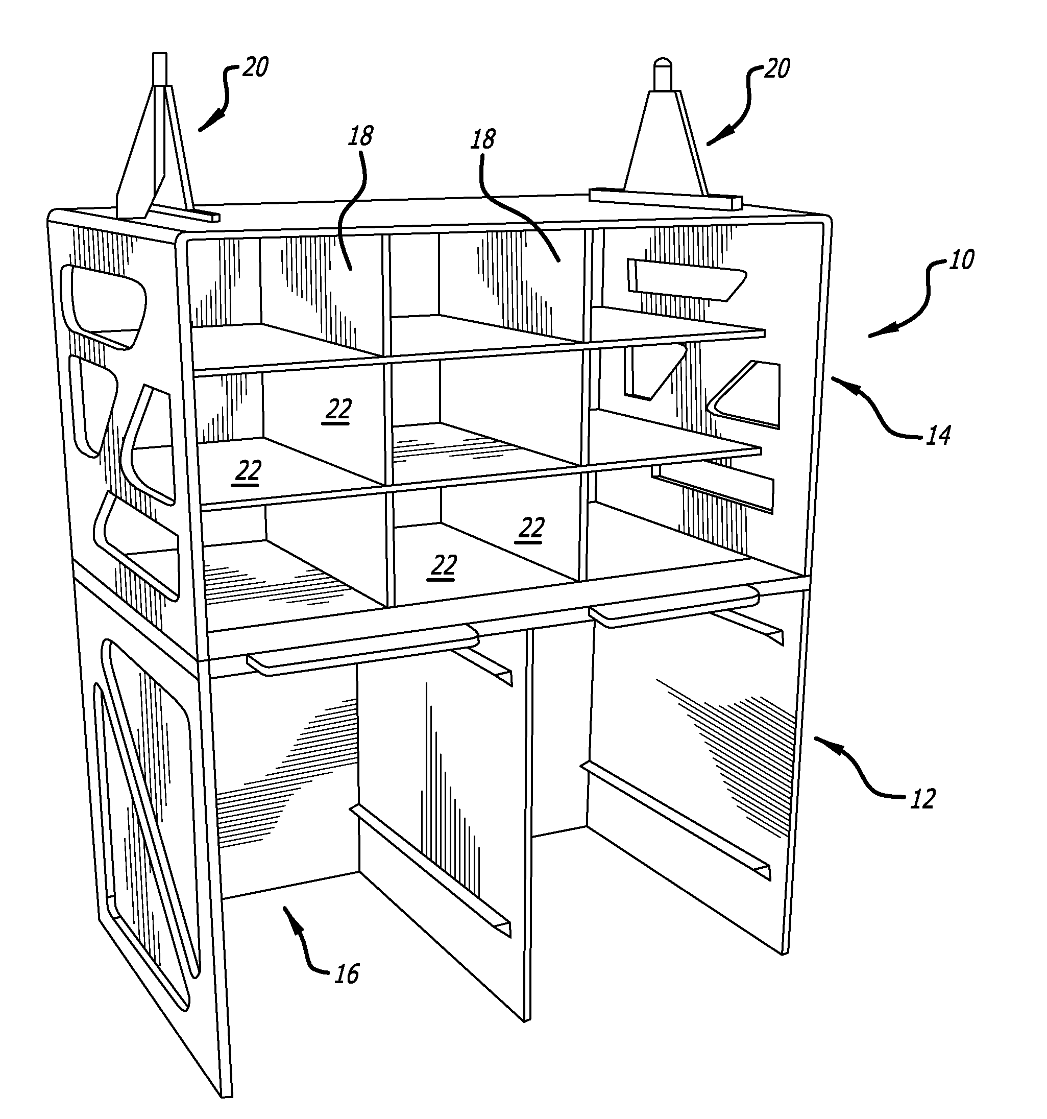
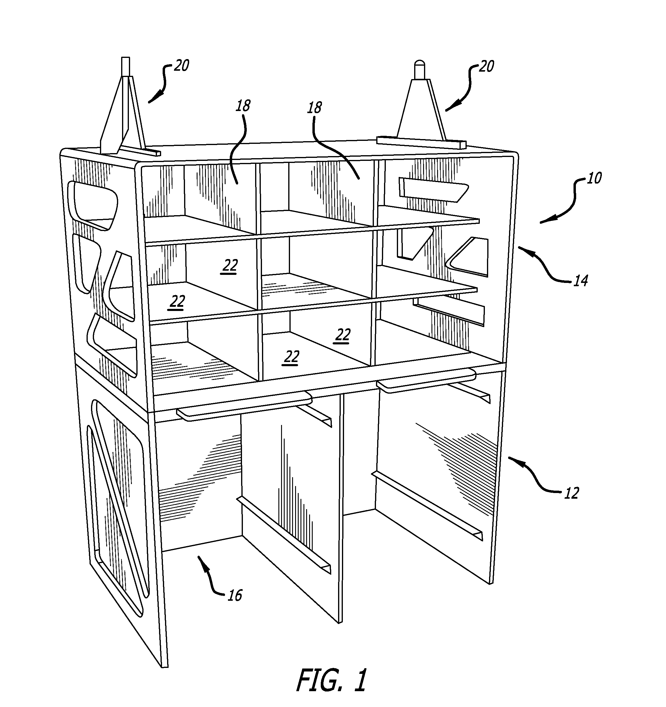
[0023]FIGS. 1 and 2 illustrate a first preferred composite aircraft monument in the form of a refrigerated center line galley 10 that comprises three main chassis sub-assemblies, a below work deck area (BWD) 12, an above work deck area (AWD) 14, and a removable, one piece rear service wall (RSW) 16. The AWD section 14 provides compartments 18 as required for galley inserts, or GAINs, such as coolers, ovens, coffee brewers, and the like to be installed. The AWD section 14 compartments 18 also provide space for meal boxes or standard units (SUs), and miscellaneous storage in the same way, together with compartment door hinge and latch locations, if so required. On top of the above work deck area 14 is a pair of composite ceiling mounts 20 for attaching the monument 10 from above to the ceiling or supporting structure of the airframe.

[0024]The compartments 18 of the above work deck 14 are defined by panels 22 as shown in FIG. 3, that is formed of previously manufactured flat CFRC-faced...


PUM


Abstract

An improved monument structure combining an integrated construction system with carbon fiber reinforced composites to form an exoskeleton chassis that significantly reduces the build times, manufacturing skill level requirements, post processing activities, and overall weight of a given aircraft monument.

Description

CROSS-REFERENCES TO RELATED APPLICATIONS[0001]This application claims priority from U.S. Provisional Patent Application No. 61 / 616,904, filed Mar. 28, 2012, incorporated herein by reference in its entirety.BACKGROUND[0002]Commercial passenger carrying airplanes commonly have storage or compartment structures (frequently referred to by the generic name “monuments”) installed on the aircraft. These structures are used in a variety of ways, such as storage of clothing and other passenger belongings, electronic entertainment centers, sleeping quarters for the officers and cabin crew, purser work stations, bar units, lavatories, and galleys used to provide in-flight catering meal service to the passengers. Traditionally, these monuments have been manufactured using multi-layered lightweight assemblies known as “sandwich panels” of Nomex® or Kevlar® cores, with resin pre impregnated fiberglass skins forming the surface. Other types of composite panels are manufactured with foam, thermo-pl...

Claims


Application Information

Patent Timeline
IPC IPC(8): B64D11/00
CPCB64D11/003Y02T50/46B64D11/04B64D11/00Y02T50/40B64D11/0007B64D11/0015B64D2011/0046B64D2011/0076
Inventor BURD, PETER JOHN LESLIE
Owner BE AEROSPACE INCORPORATED
Why Eureka
Try Eureka