
Electric motor and electrical apparatus equipped with same

a technology of electric motors and electrical equipment, which is applied in the direction of motor/generator/converter stoppers, dynamo-electric converter control, instruments, etc., can solve the problems of increasing the induced voltage in the driving coil, increasing the axial torque, increasing the rotation speed, etc.

Inactive Publication Date: 2013-10-03
PANASONIC INTELLECTUAL PROPERTY MANAGEMENT CO LTD
View PDF4 Cites 3 Cited by
  • Summary
  • Abstract
  • Description
  • Claims
  • Application Information

AI Technical Summary

Benefits of technology

The electric motor described in this patent text has a structure that increases the torque it generates at higher speeds and can change its air gap size based on humidity levels. This means that the motor can control the amount of air it produces without needing a microcomputer or specific sensor, resulting in increased air quantities with constant air-volume control.

Problems solved by technology

Further, at higher humidity than a reference humidity, the magnetic pole portion in the magnet rotor absorbs moisture to swell, which makes the air gap smaller, thereby increasing the induced voltage induced in the driving coil.

Method used


Image

  • Electric motor and electrical apparatus equipped with same
  • Electric motor and electrical apparatus equipped with same
  • Electric motor and electrical apparatus equipped with same

Examples


Embodiment Construction

[0021]Hereinafter, embodiments of the present invention will be described, with reference to the accompanying drawings.

Exemplary Embodiment

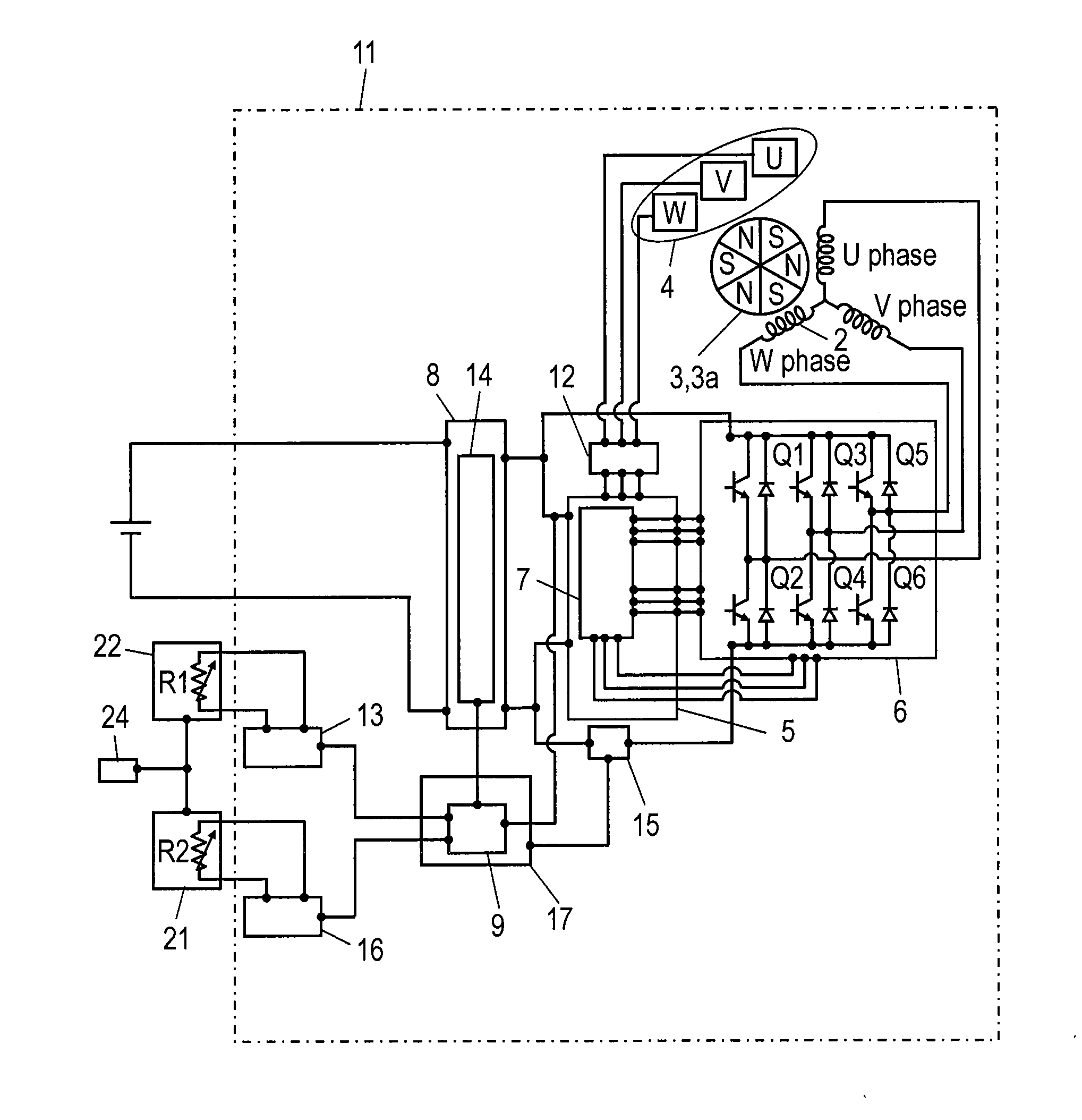
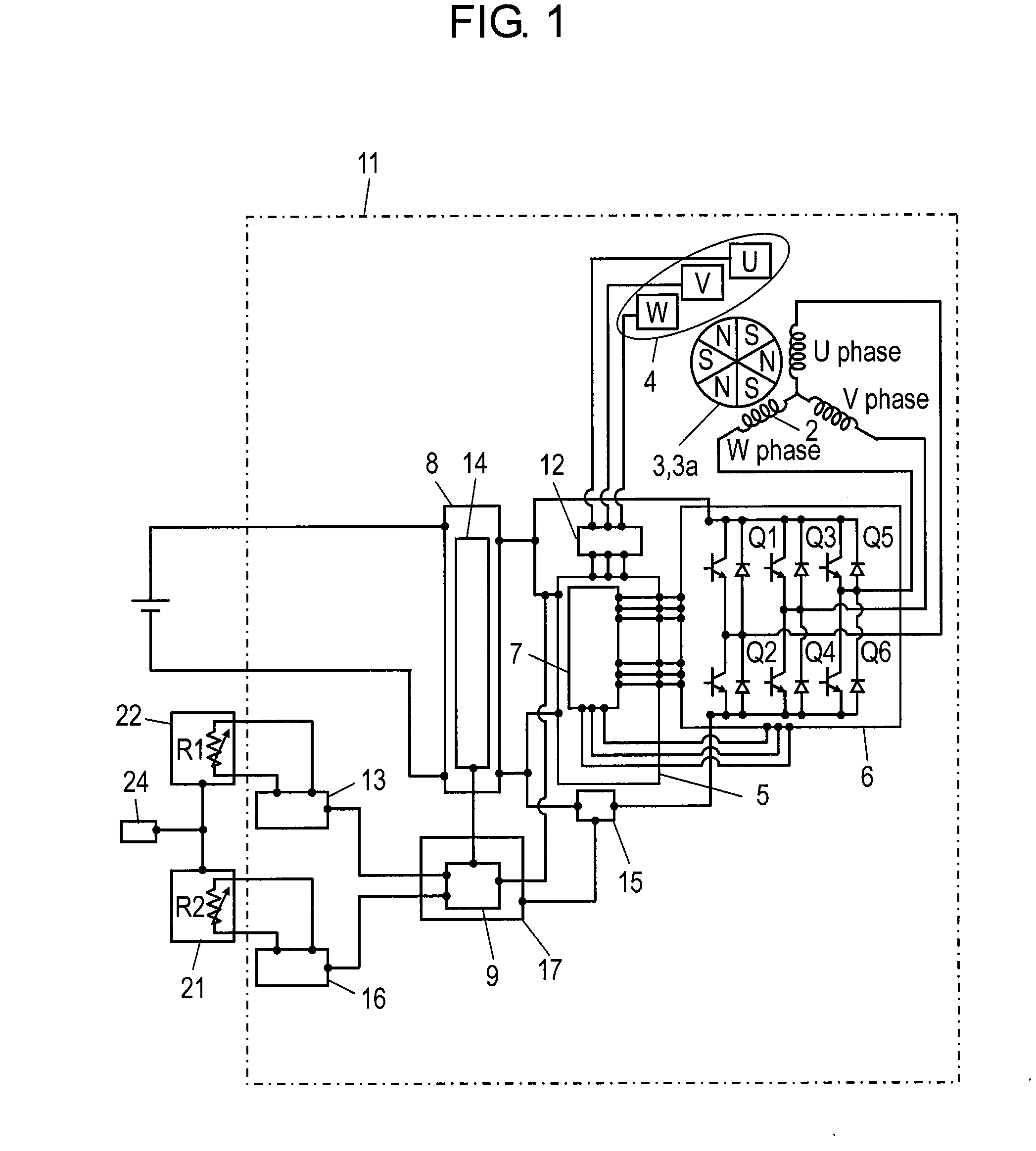
[0022]FIG. 1 is a block diagram illustrating an electric motor according to an embodiment of the present invention. Electric motor 11 includes magnet rotor 3, inverter circuit 6, DC-voltage conversion portion 8, driving logic control portion 5, supply current value control portion 17, current value designation portion 9, reference current value designation portion 16, and correlation designation portion 13. Magnet rotor 3 in electric motor 11 includes magnetic pole portion 3a which is constituted by a plastic magnet containing polyamide 6 resin as a main binder and, further, containing an elastomer as an auxiliary binder, wherein polyamide 6 resin has a smaller number of methylene groups per single amide group. Further, magnetic pole portion 3a is constituted by a polar anisotropic magnet generated by performing pole orientation during injection ...


PUM


Abstract

An electric motor includes a magnet rotor which is placed with an air gap interposed between it and a stator and has a magnetic pole portion formed from a plastic magnet which swells by hydrogen bonds, an inverter circuit, a DC-voltage conversion portion, a driving logic control portion, a supply current value control portion, a current value designation portion, a reference current value designation portion, and a correlation designation portion, wherein the correlation designation portion determines an average current value by changing the average current value linearly or non-linearly with respect to a reference current value, and the magnetic pole portion absorbs moisture to swell, thereby making the air gap smaller, at higher humidity than a reference humidity.

Description

TECHNICAL FIELD[0001]The present invention relates to electric motors and electrical apparatuses equipped with the same.BACKGROUND ART[0002]In recent years, electric motors mounted in electrical apparatuses, such as ventilation apparatuses, are required to have preferable controllability, in addition to inexpensiveness, higher efficiencies and quietness. In this case, electric motors having preferable controllability refer to those which are capable of ventilation with optimum air quantities, depending on the conditions of rooms, without being influenced by pressure losses caused by duct pipe shapes and by pressure-loss changes caused by external wind pressures or clogging in filters and the like. PTL 1 discloses the structure of a conventional electric motor of this type.[0003]Hereinafter, with reference to FIG. 11, a conventional electric motor will be described. FIG. 11 is a block diagram illustrating the conventional electric motor. As illustrated in FIG. 11, electric motor 101 ...

Claims


Application Information

Patent Timeline
Patent Type & Authority Applications(United States)
IPC IPC(8): H02P7/06
CPCH02K1/02H02K1/2753H02K21/16H02P7/06H02K2213/09H02P6/085H02K2201/03
Inventor TAKADA, MASAYUKI
Owner PANASONIC INTELLECTUAL PROPERTY MANAGEMENT CO LTD
Learn More