Output driver, electrical device having the output driver, and method of evaluating the output driver

a technology of output driver and output, which is applied in the field of output driver, can solve the problems of deterioration of output accuracy in normal operation, and achieve the effect of reducing the number of output errors, and increasing the circuit siz

Inactive Publication Date: 2013-10-03
LAPIS SEMICON CO LTD
View PDF1 Cites 1 Cited by
  • Summary
  • Abstract
  • Description
  • Claims
  • Application Information

AI Technical Summary

Benefits of technology

[0017]In the present invention, it is possible to provide the output driver capable of performing an evaluation test without increasing a circuit size or deteriorating the output accuracy. Further, it is possible to provide the electrical device having the output driver and the method of evaluating the output driver without increasing a circuit size or deteriorating the output accuracy.

Problems solved by technology

When an output amplifier is provided on a later stage relative to the D / A converter in the conventional output driver disclosed in Patent Reference, the following problems may occur.
Further, when the conventional output driver is configured to be capable of receiving both the processed data and the evaluation result data, the output accuracy tends to be deteriorated in the normal operation.

Method used


Image

  • Output driver, electrical device having the output driver, and method of evaluating the output driver
  • Output driver, electrical device having the output driver, and method of evaluating the output driver
  • Output driver, electrical device having the output driver, and method of evaluating the output driver

Examples


first embodiment

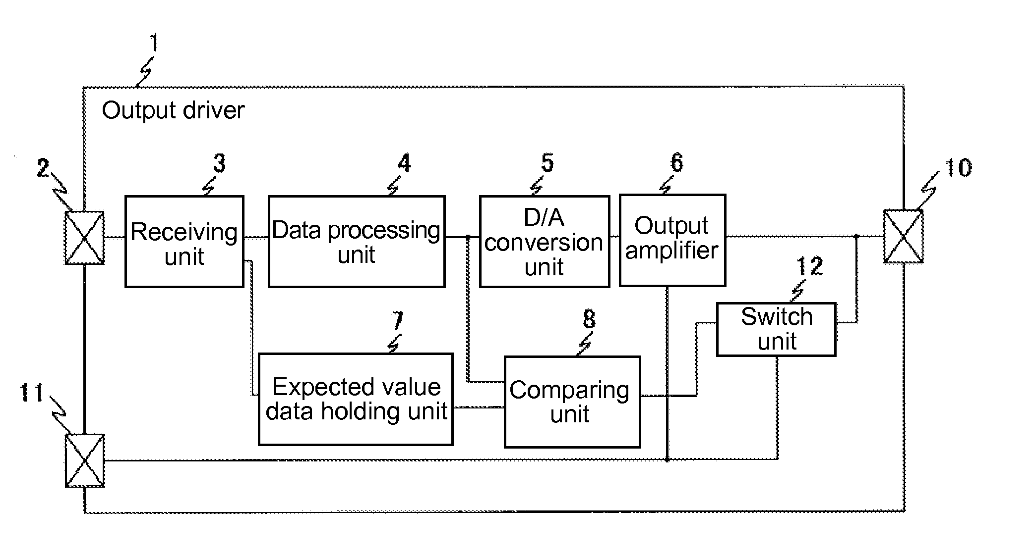
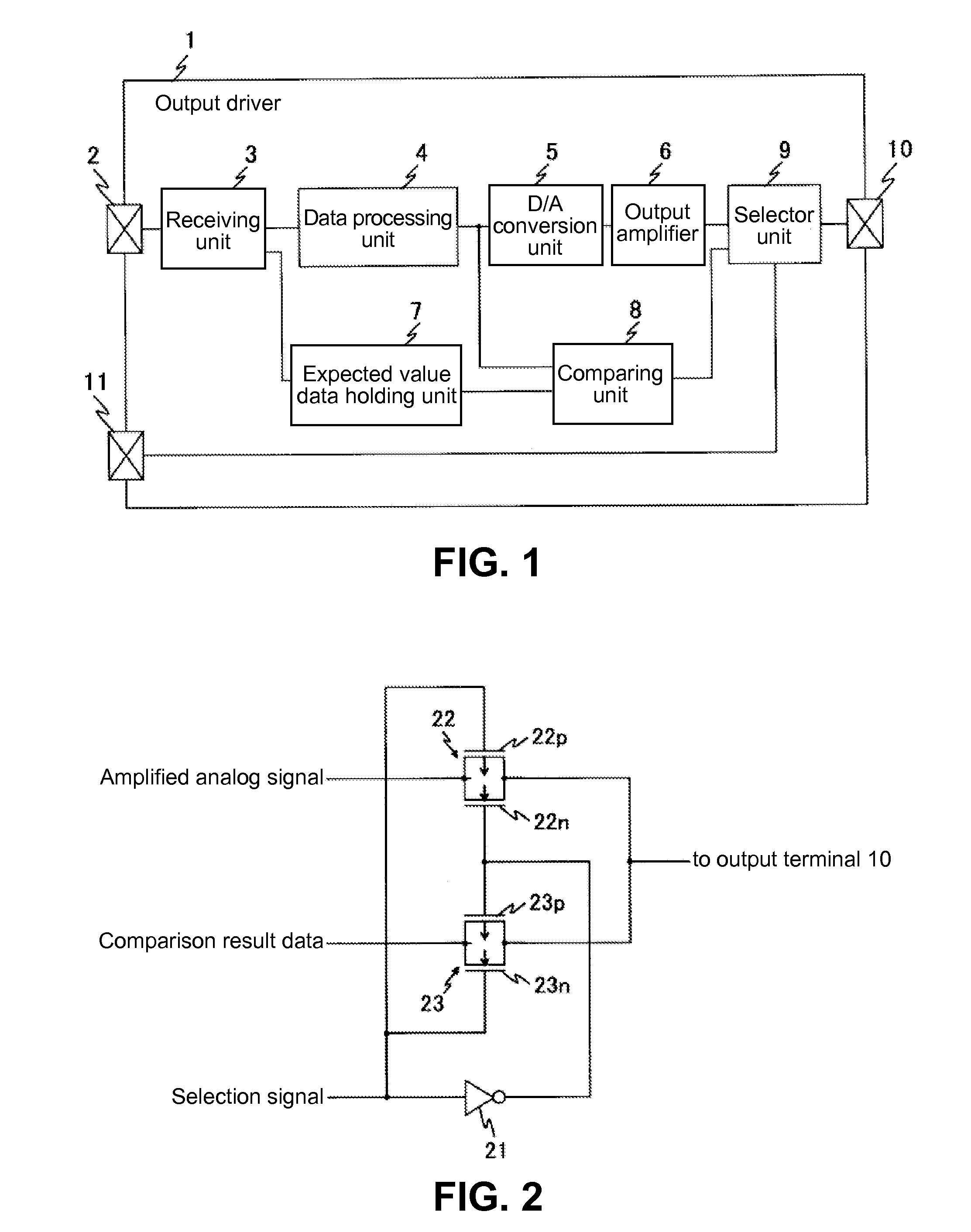
[0024]A first embodiment of the present invention will be explained. FIG. 1 is a block diagram showing a configuration of an output driver 1 according to the first embodiment of the present invention.

[0025]As shown in FIG. 1, the output driver 1 includes a receiving unit 3 for receiving a control signal input into a signal input terminal 2, so that the receiving unit 3 supplies the control signal to a data processing unit 4 arranged at a later stage thereof. The control signal includes, for example, a data signal and a clock signal for controlling, for example, a display panel (not shown in FIG. 1) of an automobile navigation system and the like.

[0026]In the first embodiment, the receiving unit 3 is configured to receive expected value data input into the signal input terminal 2, and to supply the expected value data to an expected value data holding unit 7. The expected data is data to be compared with digital data (hereunder, referred to as processing result data) that is obtained...

second embodiment

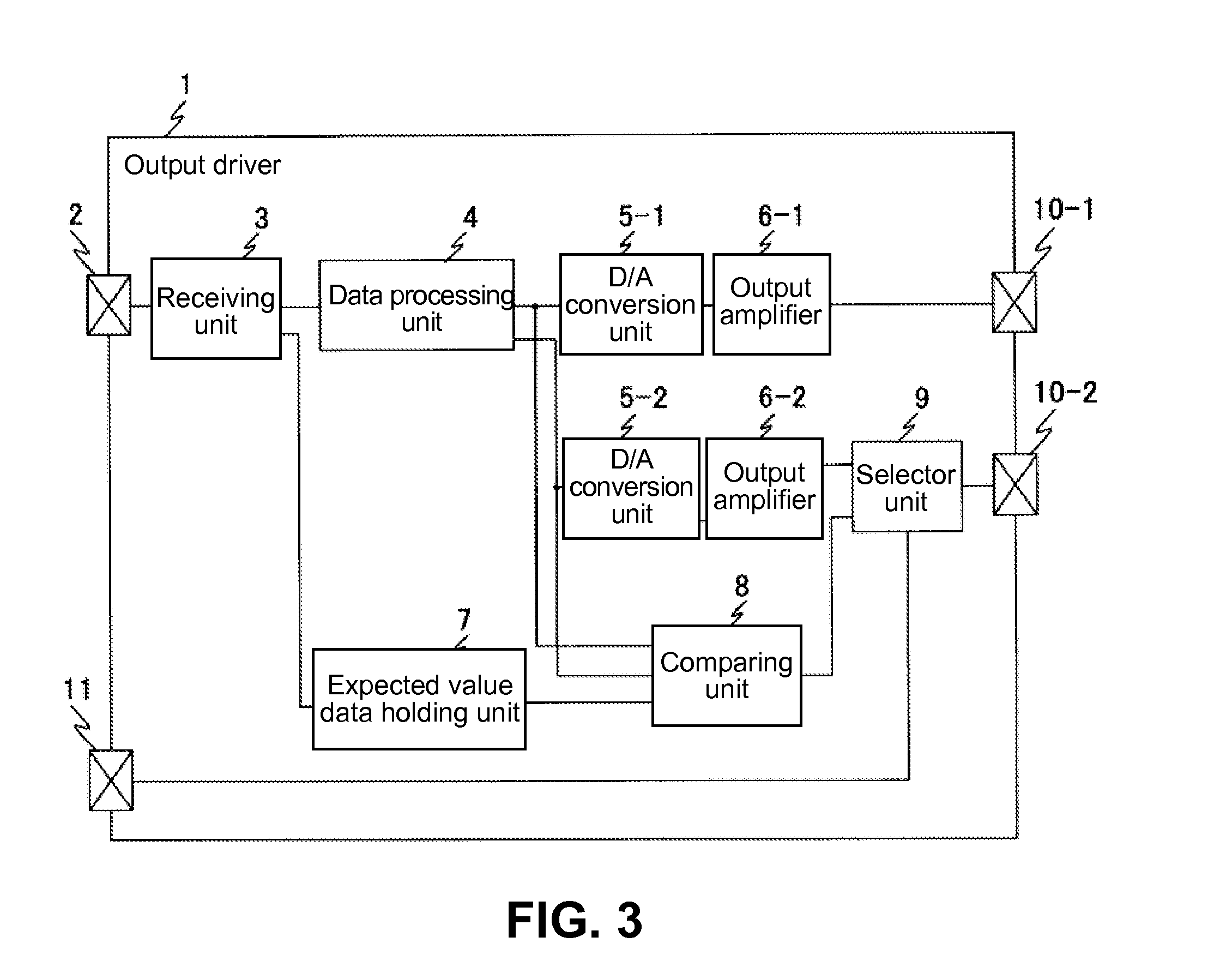
[0048]A second embodiment of the present invention will be explained next. FIG. 3 is a block diagram showing a configuration of the output driver 1 according to the second embodiment of the present invention.

[0049]As shown in FIG. 3, the output driver 1 includes a pair of D / A (Digital-to-Analog) conversion units 5-1 and 5-2, and a pair of output amplifiers 6-1 and 6-2. The output amplifier 6-1 is connected to an output terminal 10-1, and the selector unit 9 is connected to an output terminal 10-2.

[0050]In the second embodiment, the data processing unit 4 is configured to output the processing result data with a plurality of bits, and the comparing unit 8 is configured to compare simultaneously with respect to each of the bits of the processing result data. Further, the expected value data holding unit 7 is configured to hold the expected value data with a plurality of bits corresponding to each of the bits of the processing result data. More specifically, the output driver 1 has the...

third embodiment

[0052]A third embodiment of the present invention will be explained next. FIG. 4 is a block diagram showing a configuration of the output driver 1 according to the third embodiment of the present invention. In the following description, a difference from the first embodiment will be mainly explained.

[0053]As shown in FIG. 4, the output driver 1 includes a switch unit 12 as an output control unit. An output terminal of the output amplifier 6 is directly connected to the output terminal 10. In the third embodiment, when the selection signal supplied through the selection signal input terminal 11 is the low “L” level, that is, the normal mode, the output amplifier 6 outputs the amplified analog signal. When the selection signal is the high “H” level supplied through the selection signal input terminal 11, that is, the evaluation mode, the output amplifier 6 stops outputting the amplified analog signal.

[0054]In the third embodiment, an output terminal of the comparing unit 8 is connecte...


PUM


Abstract

An output driver includes a data processing unit configured to perform a data processing on an input signal to generate processing result data; a D/A (Digital-to-Analog) conversion unit configured to apply D/A conversion on the processing result data to generate an analog signal; an output amplifier configured to amplify the analog signal to obtain an amplified analog signal as an output signal; a comparing unit configured to compare the processing result data with expected value data to obtain and output comparison result data; and an output control unit configured to select the comparison result data as the output signal instead of the amplified analog signal according to a comparison output selection signal.

Description

BACKGROUND OF THE INVENTION AND RELATED ART STATEMENT[0001]The present invention relates to an output driver capable of converting input digital data to an analog signal and outputting the analog signal. Further, the present invention relates to an electrical device having the output driver and a method of evaluating the output driver.[0002]In general, a semiconductor device is provided for controlling a display panel of, for example, an automobile navigation system and the like. In the semiconductor device, an internal logic circuit is provided for processing an input signal to obtain digital data for controlling the display panel. Further, a conventional output driver is provided for converting the digital data to an analog signal, and for outputting the analog signal.[0003]Patent Reference has disclosed a configuration for evaluating a processing result of the internal logic circuit. In the configuration disclosed in Patent Reference, a selector unit is provided on a front stage ...

Claims


Application Information

Patent Timeline
Patent Type & Authority Applications(United States)
IPC IPC(8): G09G3/00H03K17/00
CPCG09G3/006H03K19/0175H03K17/00
Inventor KADOTA, DAISUKE
Owner LAPIS SEMICON CO LTD
Why Eureka
Try Eureka