
Stereoscopic image display device and driving method thereof

Inactive Publication Date: 2013-10-03
SAMSUNG DISPLAY CO LTD
View PDF5 Cites 6 Cited by
  • Summary
  • Abstract
  • Description
  • Claims
  • Application Information

AI Technical Summary

Benefits of technology

The present invention provides a stereoscopic image display device that reduces image quality deterioration due to crosstalk by displaying left-eye and right-eye images in a 3D format. Additionally, the device is produced with an economical module production cost by using low-frequency stereoscopic image driving to reduce power consumption and production costs. The driving method also reduces driving frequency to decrease power consumption and module production cost while addressing issues such as RC-delay, erroneous operation of circuit elements, and driving timing.

Problems solved by technology

If the driving frequency is increased, an incorrect image display operation may occur in the display panel, and driving power consumption of a driver of the display device generated by the high driving frequency may be increased.
This may cause an increase in the production cost of the OLED display.
Accordingly, the image quality of the stereoscopic image may be decreased such that a viewer may experience dizziness during viewing.

Method used


Image

  • Stereoscopic image display device and driving method thereof
  • Stereoscopic image display device and driving method thereof
  • Stereoscopic image display device and driving method thereof

Examples


Embodiment Construction

[0061]Embodiments of the present invention will be described more fully hereinafter with reference to the accompanying drawings, in which exemplary embodiments of the invention are shown. As those skilled in the art would realize, the described embodiments may be modified in various different ways, all without departing from the spirit or scope of the present invention.

[0062]Constituent elements having the same structures throughout the embodiments are denoted by the same reference numerals and are described in a first embodiment. In the other embodiments, only constituent elements different from those of the first embodiment will be described.

[0063]In addition, parts not related to the description are omitted for clear description of the present invention, and like reference numerals designate like elements and similar constituent elements throughout the specification.

[0064]Throughout this specification and the claims that follow, when it is described that an element is “coupled” t...


PUM


Abstract

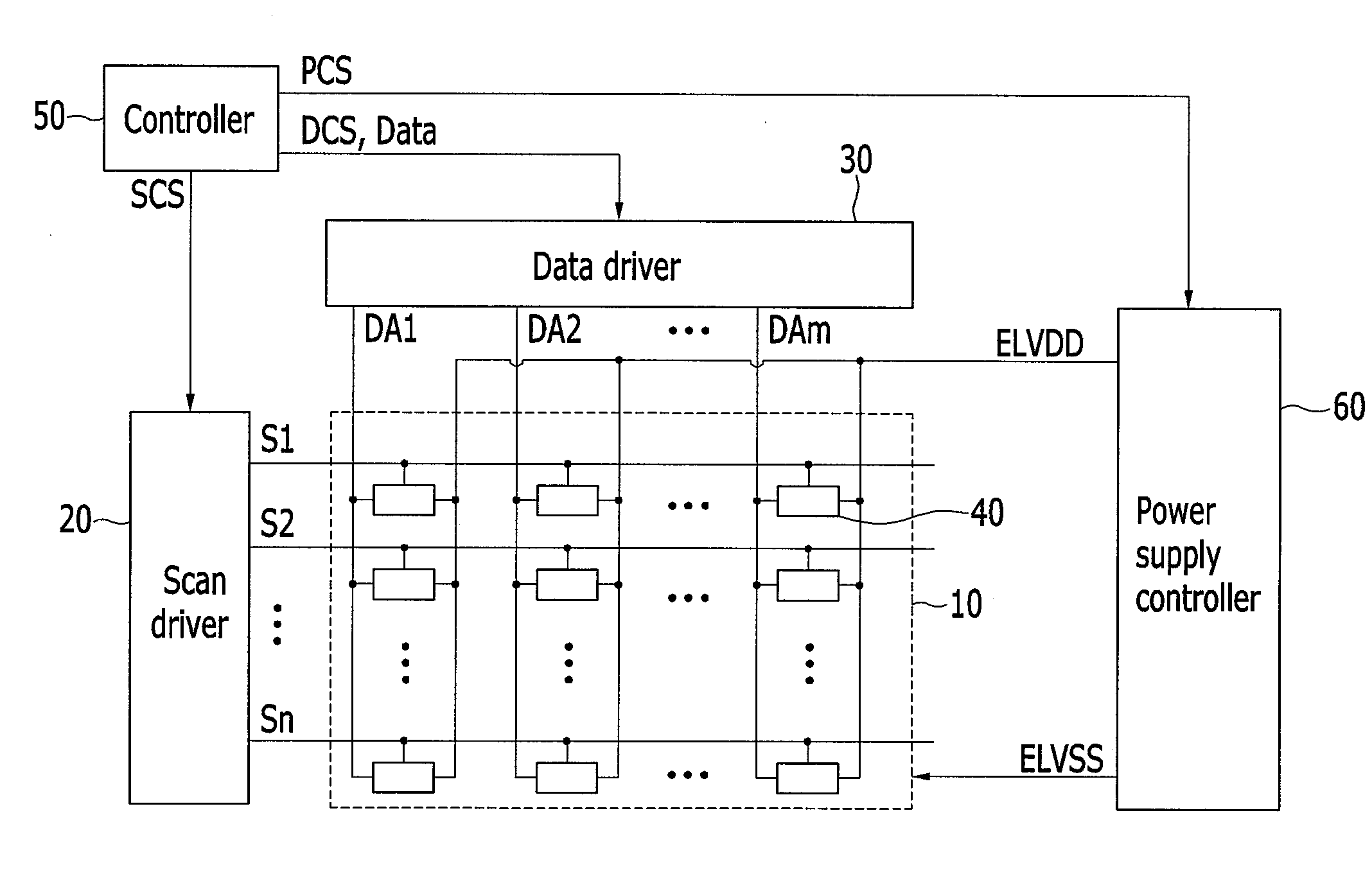
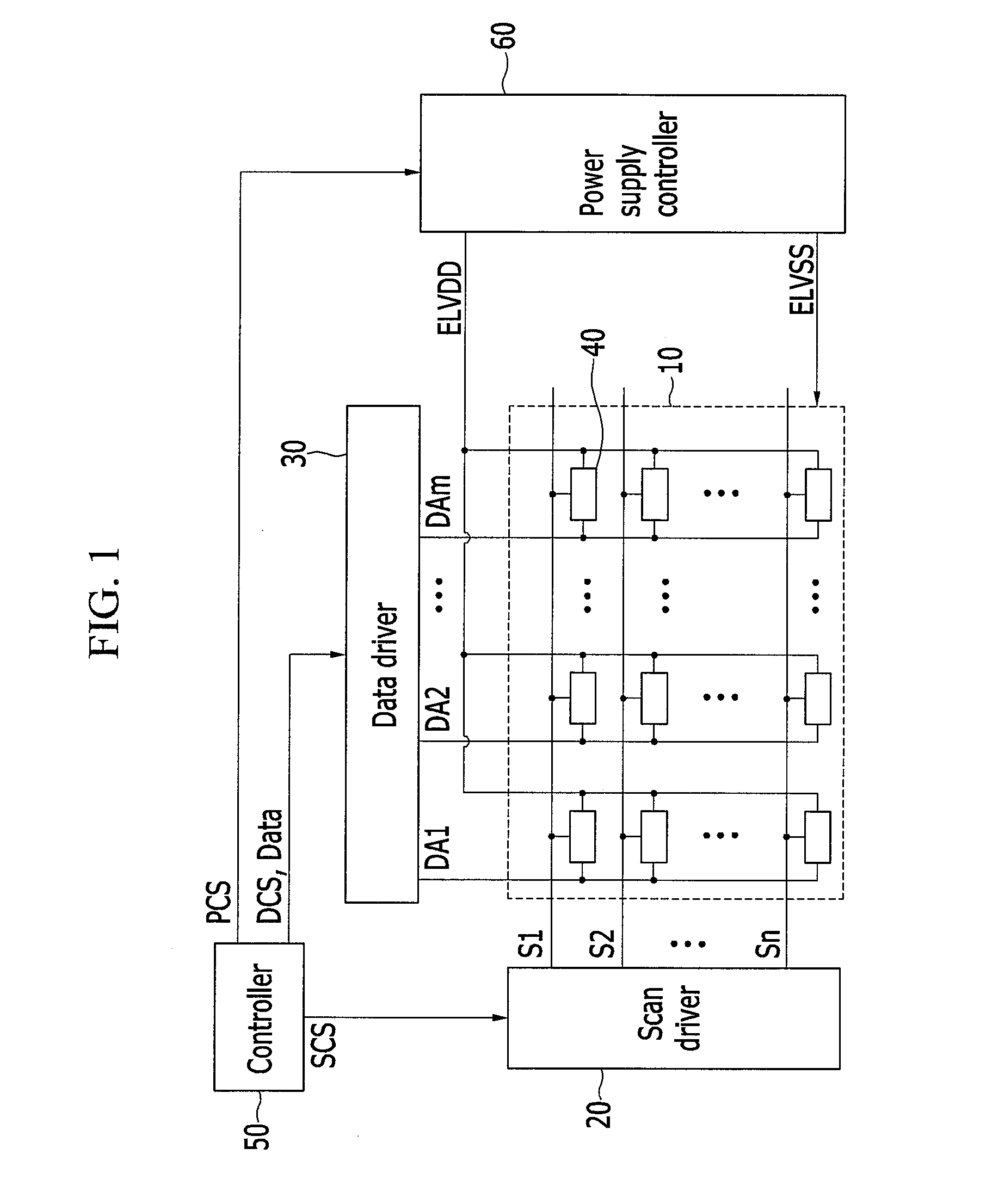
A stereoscopic image display device includes: a scan driver for transmitting scan signals to scan lines; a data driver for transmitting data signals to data lines; a display unit including pixels and configured to receive a corresponding data signal when a corresponding scan signal is transmitted to the pixels; a power supply controller for supplying a driving voltage to drive the pixels; and a controller for controlling the scan driver, the data driver, and the power supply controller, for generating an image data signal corresponding to each period of a plurality of periods, and for supplying the corresponding image data signal to the data driver. The power supply controller controls the driving voltage to block light emitting during a first view point image non-light emitting period and a second view point image non-light emitting period.

Description

CROSS-REFERENCE TO RELATED APPLICATION[0001]This application claims priority to and the benefit of Korean Patent Application No. 10-2012-0034479, filed in the Korean Intellectual Property Office on Apr. 3, 2012, the entire content of which is incorporated herein by reference.BACKGROUND[0002](a) Field[0003]Embodiments of the present invention relate to a stereoscopic image display device and a driving method thereof. More particularly, embodiments of the present invention relate to a stereoscopic image display device for realizing a stereoscopic image of high image quality and a driving method thereof.[0004](b) Description of Related Art[0005]Various flat panel displays with reduced weight and volume have been developed, and display devices using various stereoscopic image driving methods to realize 3D stereoscopic images have also been developed.[0006]Examples of the flat panel displays include a liquid crystal display (LCD), a field emission display (FED), a plasma display panel (P...

Claims


Application Information

Patent Timeline
IPC IPC(8): G02B27/22
CPCG02B27/2264G02B30/24G09G3/30
Inventor AHN, JEONG-KEUNLEE, BACK-WOONKIM, DO-IKJEONG, JOO-HYEON
Owner SAMSUNG DISPLAY CO LTD
Learn More