Systems and methods for selecting pacing vectors based on site of latest activation for use with implantable cardiac rhythm management devices

a technology of pacing vector and activation site, which is applied in the direction of electrotherapy, heart stimulators, therapy, etc., can solve the problems of micro-dislodged or even migrated, and difficult to find the optimal placement location of the implanted device, so as to simplify the clinician's workflow and reduce the amount of time and effort.

Active Publication Date: 2013-10-03
PACESETTER INC
View PDF4 Cites 16 Cited by
  • Summary
  • Abstract
  • Description
  • Claims
  • Application Information

AI Technical Summary

Benefits of technology

[0006]In an exemplary embodiment, a method is provided for use with an implantable CRT device (or other suitable implantable medical device) for identifying suitable pacing vectors for use with multi-pole LV leads. Briefly, RV-LV delay times are measured while using different electrodes of the LV lead as sensing cathodes to measure an RV-LV delay time for each LV electrode. An LV electrode is selected based on the measured RV-LV delay times, such as by selecting the LV electrode having the longest RV-LV delay time (i.e. the LV electrode located at the site of latest activation (SOLA.)) Stimulation thresholds are measured for pacing vectors that employ the selected LV electrode, such as LV capture thresholds or diaphragmatic stimulation thresholds, or both. Assuming that at least one vector employing the selected LV electrode is found to have an acceptable threshold, that vector is identified and selected for use in delivering pacing therapy with the selected LV electrode as a cathode. If none of the vectors employing the selected LV electrode has an acceptable threshold, then another LV electrode such as the electrode with the next longest RV-LV delay is selected and the procedure is repeated. In this manner, an expedited test procedure is provided wherein only a subset of the total number of possible pacing vectors is initially tested to identify acceptable pacing vectors, thereby reducing the amount of time and effort needed to identify suitable vectors and, in particular, simplifying clinician workflow. The technique exploits the use of LV electrodes as cathodes because it is believed that the cathode has a more important role in determining pacing efficacy than the anode. The expedited procedure, which may be referred to as Site Optimization (SiteOpt), is typically performed by a programmer under the supervision of a clinician. The programmer transmits suitable control signals to the CRT device, which performs the RV-LV delay time tests and capture threshold tests. However, if suitably equipped, the CRT device itself may perform the procedure independent of the programmer so as to automatically take advantage of electronic repositioning, where appropriate. This technique, which exploits a multi-pole LV lead, is particularly advantageous for use within patients with left bundle branch block (LBBB) where the SOLA is located in the LV. For patients where the SOLA is instead located in the RV (such as patients with right bundle branch block (RBBB)), an alternative procedure that exploits a multi-pole RV lead may be used. The multi-pole LV lead example is the primary example described herein since most heart failure patients have LBBB.

Problems solved by technology

CRT device implant can be challenging, for example, when the left ventricular (LV) lead is placed intravenously, advancing through the coronary sinus (CS) and into a selected branch of the cardiac venous system.
It can be difficult to find an optimal location for placement of the lead due to patient variability in venous anatomy.
A further challenge, after lead implant, is that positional changes may cause the lead to be micro-dislodged or even migrated.
Likewise, if lead migration or other factors cause the LV capture threshold to increase, then an LV pacing pulse initially set to a pulse magnitude sufficient to depolarize the LV may fail to do so.
However, a quadripolar LV lead offers numerous programmable pacing / sensing vectors and so testing the capture thresholds and diaphragmatic stimulation thresholds for the entire set of programmable vectors can be complicated and time consuming.
In particular, the workflow that a clinician typically must go through to perform and manage the various tests to identify suitable pacing vectors can be complex and time consuming.

Method used


Image

  • Systems and methods for selecting pacing vectors based on site of latest activation for use with implantable cardiac rhythm management devices
  • Systems and methods for selecting pacing vectors based on site of latest activation for use with implantable cardiac rhythm management devices
  • Systems and methods for selecting pacing vectors based on site of latest activation for use with implantable cardiac rhythm management devices

Examples


Embodiment Construction

[0027]The following description includes the best mode presently contemplated for practicing the invention. This description is not to be taken in a limiting sense but is made merely to describe general principles of the invention. The scope of the invention should be ascertained with reference to the issued claims. In the description of the invention that follows, like numerals or reference designators will be used to refer to like parts or elements throughout.

Overview of Implantable Systems and Methods

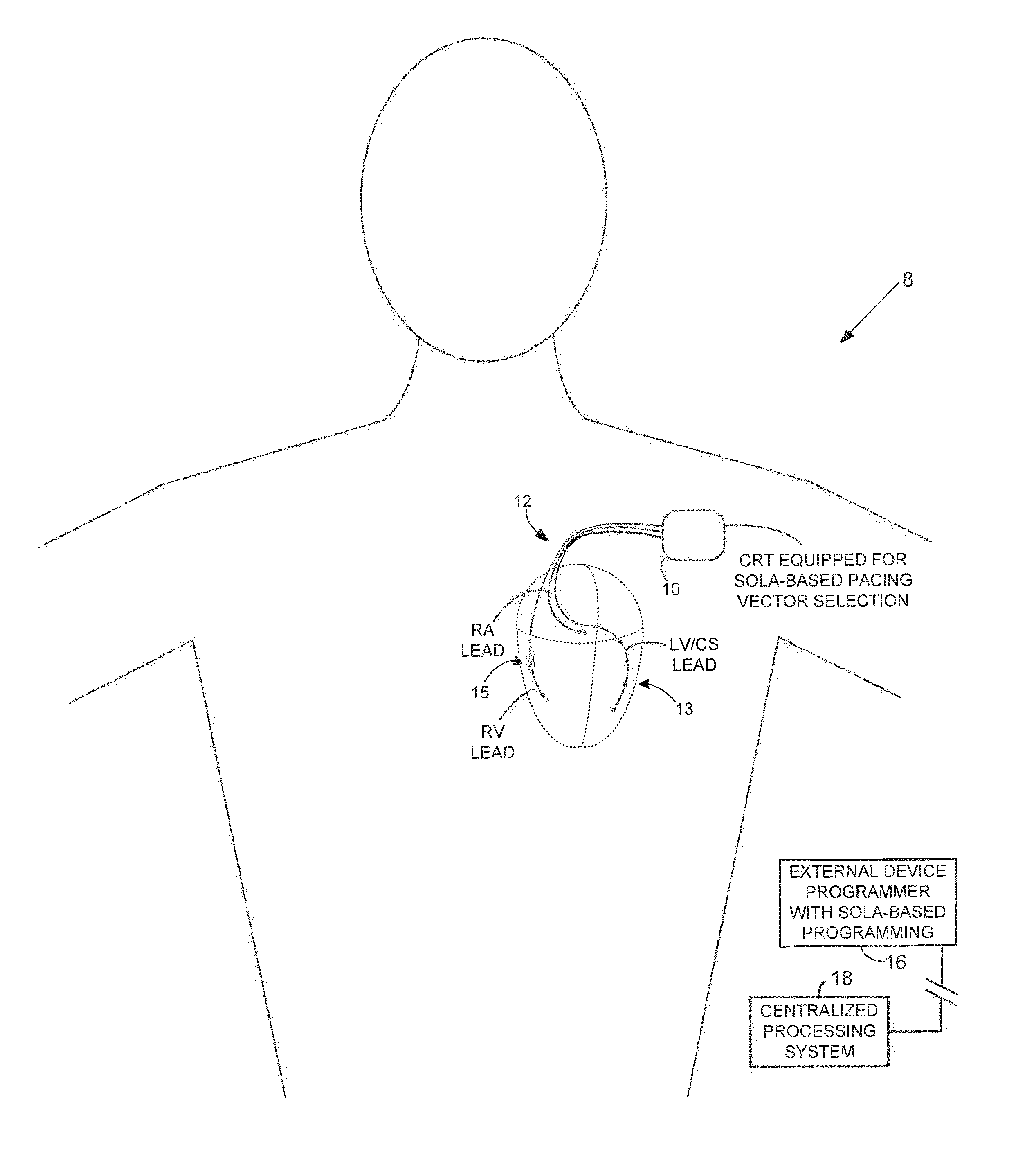
[0028]FIG. 1 illustrates an implantable medical system 8 equipped for expedited identification of suitable pacing vectors (alone or in conjunction with an external programmer.) In this example, the implantable medical system 8 includes a CRT device 10 (which may be a pacer, ICD, CRT or other suitable device) equipped with a set of cardiac sensing / pacing leads 12 implanted on or within the heart of the patient, including a multi-pole LV lead implanted via the CS. In FIG. 1, a stylized...


PUM


Abstract

Techniques are provided for use with an implantable cardiac stimulation device equipped with a multi-pole left ventricular (LV) lead and a right ventricular (RV) lead for identifying suitable pacing vectors. In one example, RV-LV delay times are measured while using different electrodes of the LV lead as cathodes for sensing. The LV electrode having the longest RV-LV delay time is identified and LV capture thresholds and diaphragmatic stimulation thresholds are measured for pacing vectors that employ that LV electrode as a cathode. Assuming at least one vector employing the selected LV electrode is found to have acceptable thresholds, the vector is selected for use in delivering pacing therapy with the selected LV electrode. If none of the pacing vectors employing the selected LV electrode has acceptable thresholds, another LV electrode is selected and the procedure is repeated. Examples with a multi-pole RV lead are also described.

Description

FIELD OF THE INVENTION[0001]The invention relates to implantable cardiac rhythm management devices (CRMDs) such as cardiac resynchronization therapy (CRT) devices or implantable cardioverter-defibrillators (ICDs) and, in particular, to techniques for selecting pacing vectors for use with CRT.BACKGROUND OF THE INVENTION[0002]CRT device implant can be challenging, for example, when the left ventricular (LV) lead is placed intravenously, advancing through the coronary sinus (CS) and into a selected branch of the cardiac venous system. It can be difficult to find an optimal location for placement of the lead due to patient variability in venous anatomy. A further challenge, after lead implant, is that positional changes may cause the lead to be micro-dislodged or even migrated. This may result in a decrease of the diaphragmatic stimulation threshold (i.e. the threshold above which a stimulation pulse delivered using the lead inadvertently triggers contraction of diaphragmatic muscles) a...

Claims


Application Information

Patent Timeline
Patent Type & Authority Applications(United States)
IPC IPC(8): A61N1/368
CPCA61N1/3686
Inventor XI, CECILIA QINGAVALES, DIANAMILLER, ANDREWMCGARVEY, ANDREW W.BRIGGS, ZACHARYBISHOP, DAVIDSTANDAGE, SHARONKENI, ANILBLOCK, RICHARDHELLMAN, HEIDISMITH, TARYN
Owner PACESETTER INC
Why Eureka
Try Eureka