
Stent holding structure for introducers

a technology of introducers and stents, applied in the field of stent holding structures for introducers, can solve the problems of affecting the assembly of devices, and affecting the movement of medical devices, so as to improve the assembly of introducers, improve the stent holding structure, and improve the medical device carrier

Inactive Publication Date: 2013-10-03
COOK MEDICAL TECH LLC
View PDF1 Cites 3 Cited by
  • Summary
  • Abstract
  • Description
  • Claims
  • Application Information

AI Technical Summary

Benefits of technology

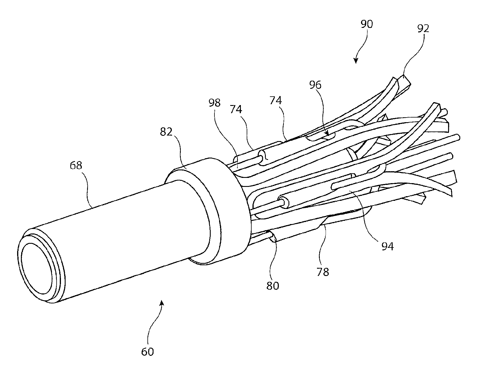
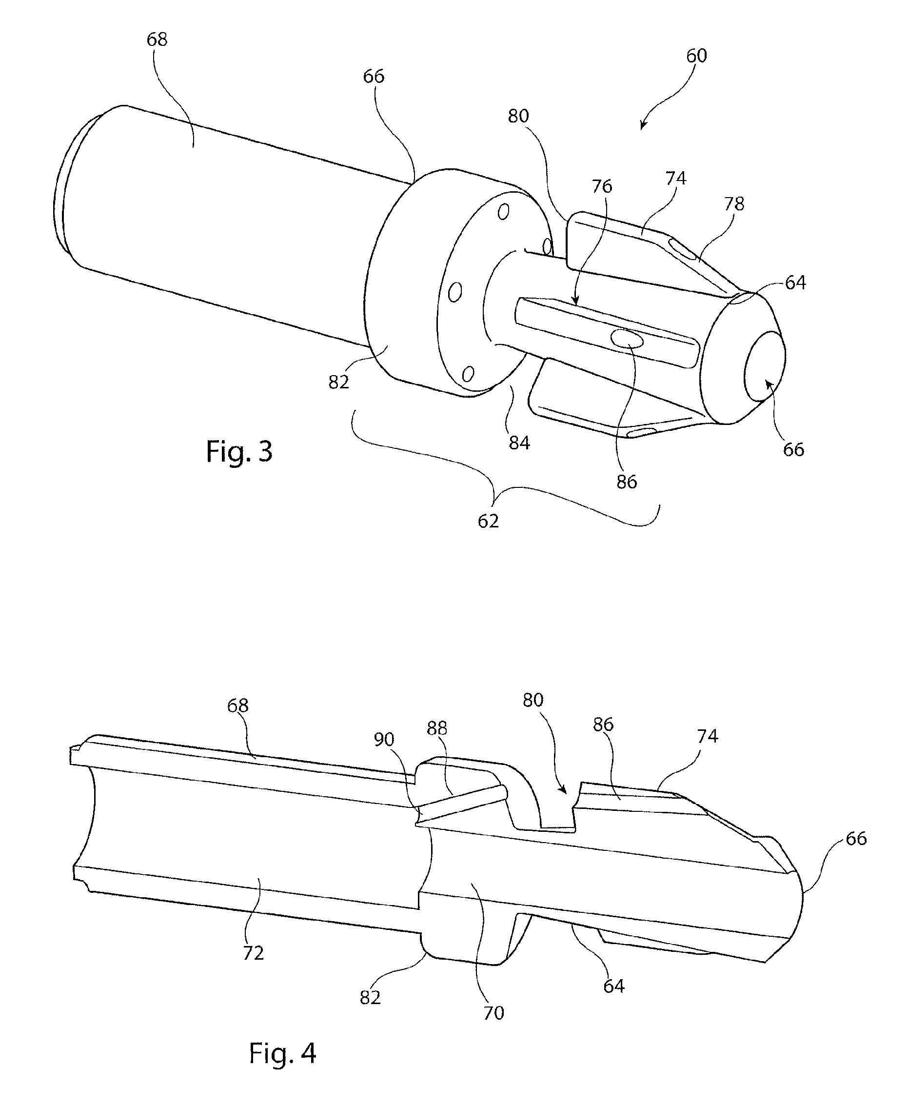
The present invention introduces an improved stent holding structure for introducers, an improved medical device carrier and an improved introducer assembly. The invention utilizes ribs or fins on the carrier to hold the medical device securely, allowing for some movement of the device during deployment without losing positional stability or orientation. The shoulder of the ribs reduces stresses on restraining elements and facilitates easier and more reliable release of the device from the carrier during the deployment operation. The medical device carrier includes a plurality of ribs that provide multiple support points for the device, further securing it to the carrier. The carrier element includes a distal end for insertion into a patient and a proximal end, wherein the shoulder acts to pull the device rather than compress it, reducing the chance of distortion of the device. The carrier also includes a bore, channel or groove in the ribs, ensuring straight trigger wires at the time of deployment and easier removal. These technical improvements enhance the stability and reliability of the medical device delivery system.

Problems solved by technology

The length of the introducer assembly and path it takes through the vasculature of the patient can cause positional difficulties with regard to the device and can cause the device to distort within the assembly.
Moreover, where trigger wires are used, these tend to distort as a result of the stresses under which they are put, these stresses being caused by: a) the tendency of the medical device to expand, b) the manner in which the trigger wires are held in the assembly, and c) the operating forces to which they are subjected.
Distortion of the trigger wires can lead to movement of the medical device and difficulty in releasing it from the introducer.

Method used


Image

  • Stent holding structure for introducers
  • Stent holding structure for introducers
  • Stent holding structure for introducers

Examples


Embodiment Construction

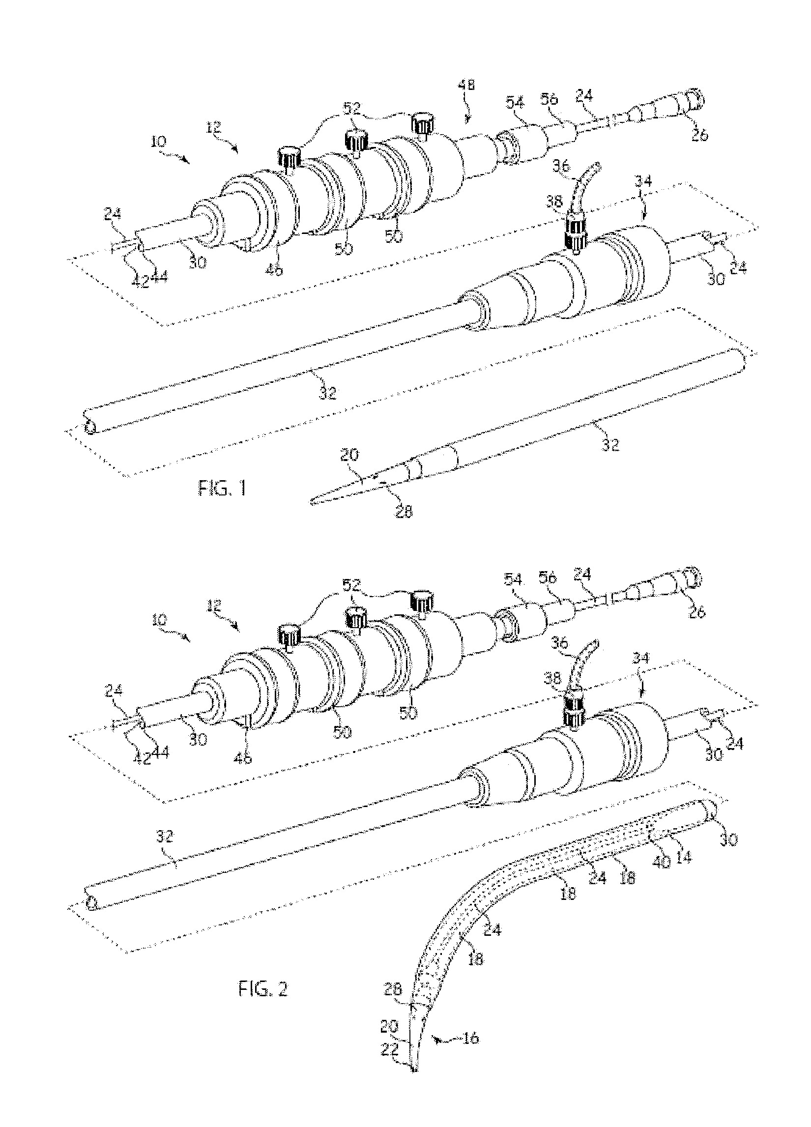
[0027]It is to be appreciated that the drawings of this application are intended to be schematic and do not show the components of the introducer assembly to their intended scale. In Figures the components are shown in enlarged form for the purposes of clarity only.

[0028]It is also to be appreciated that although the embodiments described below focus on the deployment of a stent, the structure of introducer assembly taught herein can be used for the deployment of a wide variety of medical devices including but not limited to stents, stent grafts, vena cava filters, occluders and so on.

[0029]Referring to FIGS. 1 and 2, the example of known introducer assembly 10 shown includes an external manipulation section 12, a distal attachment region 14 and a proximal attachment region 16. The distal attachment region 14 and the proximal attachment region 16 secure the distal and proximal ends of an implantable medical device 18, respectively. During the medical procedure to deploy the implant ...


PUM


Abstract

An implantable medical device includes a carrier element having a distal holding member (60) which includes a proximal connecting element (64) which is attached to a guidewire catheter (24) and a distal connecting element (68) which is attached to a dilator tip (20). A proximal connecting element (64) includes a plurality of ribs (74) which have a perpendicular shoulder (80) spaced from an enlarged head (82). The shoulder (80) supports and endmost stent (92) of a device held by the distal holding member (60). Guide wires (98) pass through lumens (86, 88) in the ribs (74) and enlarged head (82), these guidewires (98) being substantially straight. The ribs (74) support an implantable medical device both in the longitudinal direction and in the radial direction. The device (90) can also be pulled rather than pushed by means of the introducer assembly.

Description

[0001]This application claims the benefit of the filing date of United Kingdom (GB) patent application number 1205719.6, filed Mar. 30, 2012, which is hereby incorporated by reference herein.TECHNICAL FIELD[0002]The present invention relates to a stent holding structure for introducers, to a medical device carrier and to an introducer assembly for the deployment of implantable medical devices such as stents, stent grafts, vena cava filters and so on.BACKGROUND ART[0003]Endoluminally implantable medical devices, such as stents, stent grafts, vena cava filters and the like, tend to be deployed into a patient via an elongate introducer assembly which is passed endoluminally through the vasculature of the patient. For instance, in the case of an aortic implantable medical device, this may be introduced via the femoral artery and passed up to the aorta for deployment. Such introducer assemblies typically comprise at least one catheter or carrier element and an outer protective sheath. Th...

Claims


Application Information

Patent Timeline
Patent Type & Authority Applications(United States)
IPC IPC(8): A61F2/95
CPCA61F2/966A61F2/95A61F2002/9665A61F2002/9511A61F2/2427
Inventor HENDRIKSEN, PERRASMUSSEN, ERIK E.DIERKING, WILLIAM KURT
Owner COOK MEDICAL TECH LLC
Learn More