Control valve driven by stepping motor

a technology of stepping motor and control valve, which is applied in the direction of valve operating means/releasing devices, mechanical equipment, transportation and packaging, etc., can solve the problems of increasing the space of the motor to be installed in the vehicle, and achieve the effect of compact size and low cos

Inactive Publication Date: 2013-10-10
TGK
View PDF5 Cites 18 Cited by
  • Summary
  • Abstract
  • Description
  • Claims
  • Application Information

AI Technical Summary

Benefits of technology

[0013]According to this embodiment, a valve actuating member, configured to drive a valve element in directions in which a valve section is opened and closed by converting a rotational movement of a rotor into a translational movement of the valve actuating member, is provided, and hence a displacement in the axis line direction of the rotor is not caused and a stepping motor can be formed so as to have a compact size. Further, a translational movement of the valve actuating member in the axis line direction with respect to the rotor is allowed, while a rotational movement thereof with respect to the rotor is regulated. Thereby, it can be suppressed that a reaction force in the axis line direction, which is to act on the valve actuating member from the valve element side, may be transmitted to the rotor. As a result, it is not needed to separately provide an expensive bearing for supporting the rotor in the axis line direction, and hence a control valve can be manufactured at a low cost.

Problems solved by technology

In the control valve described in, for example, Patent Document 1, however, opening and closing drive of the valve is accompanied by a translational movement of a rotor, and hence a stepping motor becomes large in size, thereby causing a problem in terms of the space of the motor to be installed in a vehicle.
In such a structure, however, a reaction force in an axis line direction, which is to act from the valve element, acts on the rotor when the valve element is driven, and hence an expensive bearing is needed for suitably supporting the rotor in the axis line direction, thereby leaving the problem that cost is increased.

Method used


Image

  • Control valve driven by stepping motor
  • Control valve driven by stepping motor
  • Control valve driven by stepping motor

Examples


first embodiment

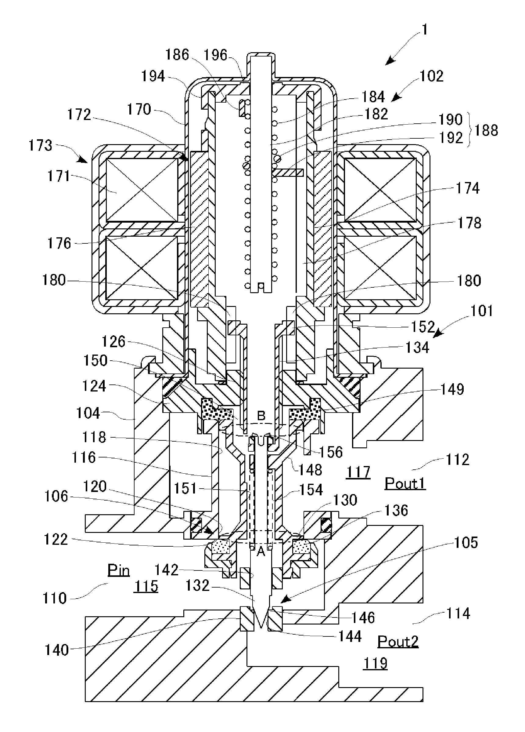
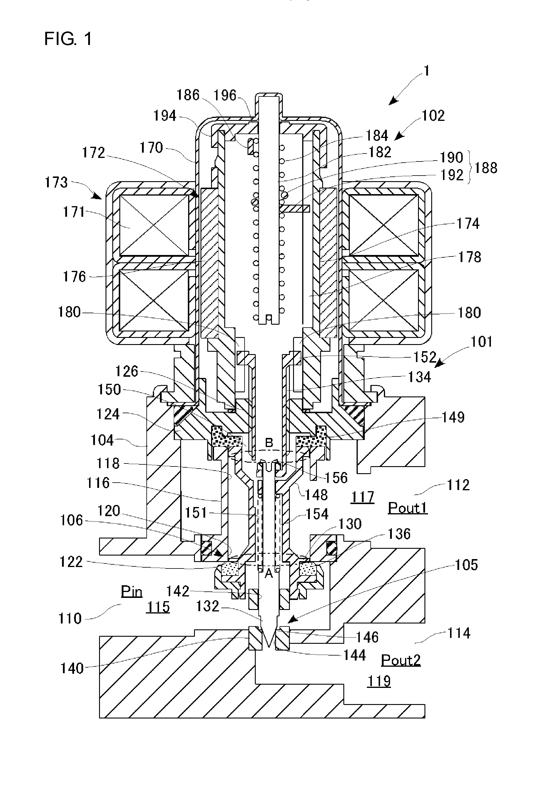
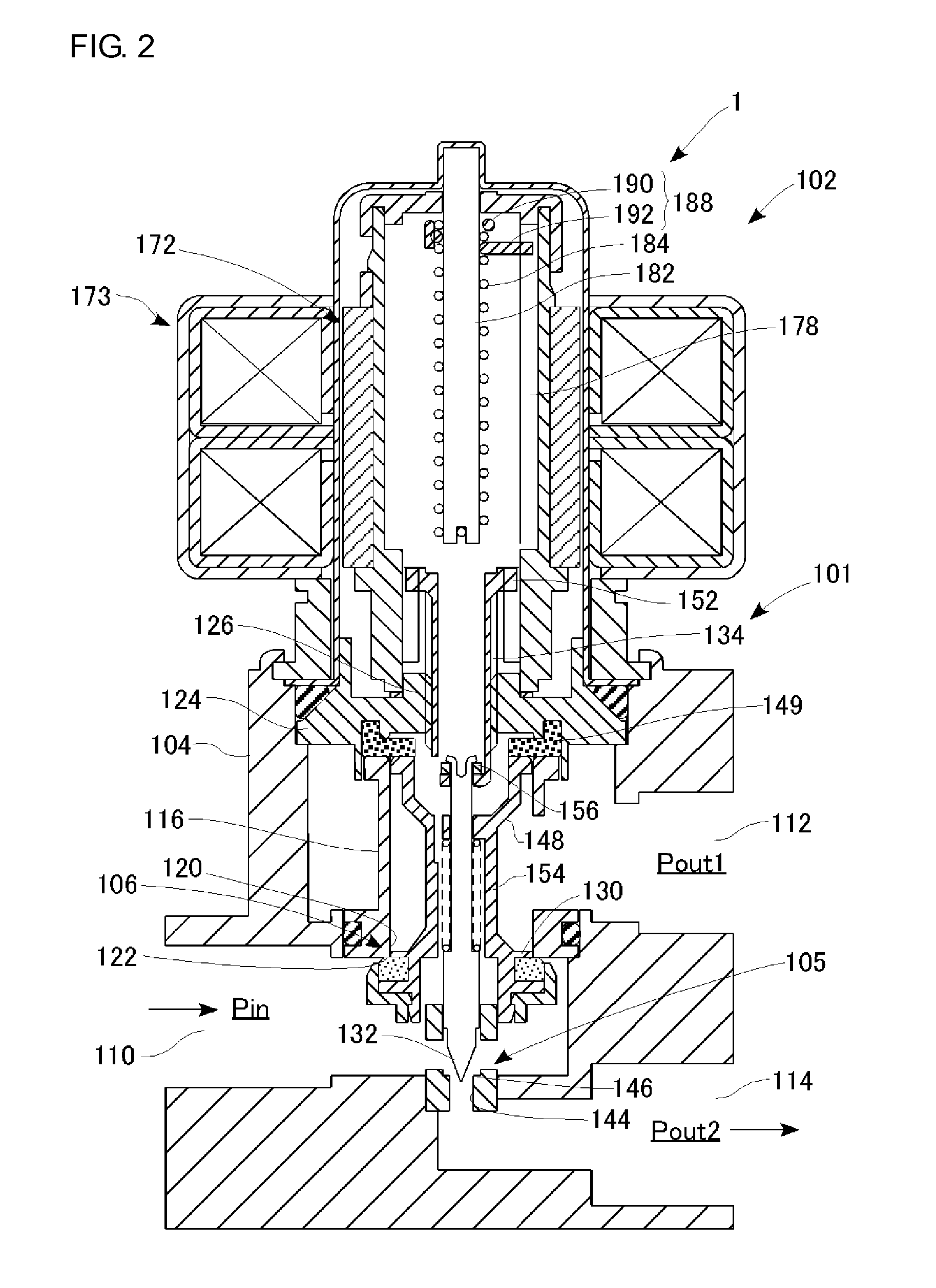
[0032]First Embodiment of the present invention will be first described. FIGS. 1 to 3 are sectional views each illustrating a structure and an operation of a control valve according to First Embodiment. The control valve according to the present embodiment is considered to be applied to an air conditioner driven by a heat pump, which is to be mounted, for example, in an electric car.

[0033]That is, a refrigeration cycle (refrigerant circulation circuit), in which a compressor, an internal condenser, an external heat exchanger, an evaporator, and an accumulator, etc., are connected together by pipes, is provided in an automotive air conditioner, and air conditioning of a vehicle interior is performed by heat exchange occurring in a course through which a refrigerant circulates the refrigeration cycle while changing its states. Various control valves for appropriately controlling the air conditioning are arranged in the refrigerant circulation circuit, and a control valve 1 forms one o...

second embodiment

[0058]Subsequently, Second Embodiment of the present invention will be described. A control valve according to the present embodiment is different from that of First Embodiment with respect to the structure of a valve mechanism, etc., but has the structures of other parts the same as those of the control valve of First Embodiment. Accordingly, parts having structures almost similar to those in First Embodiment will be denoted with like reference numerals, and descriptions thereof will be appropriately omitted. FIGS. 4 to 6 are sectional views each illustrating a structure and an operation of the control valve according to Second Embodiment.

[0059]The control valve 2 is provided at a connection point where a first passage, a second passage, and a third passage, which form the refrigerant circulation passage, are connected together, so that a flow of the refrigerant flowing through each of the passages is switched and a flow rate thereof is adjusted. In the present embodiment, the firs...

third embodiment

[0068]Subsequently, Third Embodiment of the present invention will be described. A control valve according to the present embodiment is different from those of First Embodiment and Second Embodiment with respect to the structure of a valve mechanism, etc., but has the structures of other parts the same as those of the control valves of First Embodiment and Second Embodiment. Accordingly, parts having structures almost similar to those in First Embodiment and Second Embodiment will be denoted with like reference numerals, and descriptions thereof will be appropriately omitted. FIGS. 7 to 9 are sectional views each illustrating a structure and an operation of the control valve according to Third Embodiment.

[0069]The control valve 3 is provided at a connection point where a first upstream passage, a second upstream passage, and a downstream passage, which form the refrigerant circulation passage, are connected together, so that a flow of a refrigerant flowing through each of the passag...


PUM


Abstract

A control valve includes: a body having valve holes for communicating an inlet port and the outlet ports together, respectively; valve elements for opening and closing valve sections by contacting and leaving the valve holes, respectively; a stepping motor having a rotor for driving the valve elements in the opening and closing directions of the valve sections; and a valve actuating member that drives the valve elements in the opening and closing directions of the valve sections by converting a rotational movement of the rotor around the axis line thereof into a translational movement of the valve actuating member in the axis line direction. The valve actuating member is supported by the rotor so as to be capable of making a translational movement of the valve actuating member in the axial direction with respect to the rotor, while a rotational movement with respect to the rotor is regulated.

Description

CLAIM OF PRIORITY TO RELATED APPLICATION[0001]This application claims priority under 35 U.S.C. §120 and 365 (c) as a continuation of prior International Application No. PCT / JP2011 / 005662, filed on Oct. 7, 2011, which further claims priority of Japanese Patent Application No. JP 2010-257431 filed on Nov. 18, 2010, the contents of which are incorporated herein by reference.BACKGROUND OF THE INVENTION[0002]1. Field of the Invention[0003]The present invention relates to a control valve driven by a stepping motor, and in particular, to a control valve suitable for an automotive air conditioner.[0004]2. Description of the Related Art[0005]In a vehicle in which an internal-combustion engine is mounted, it recently becomes difficult that the temperature of the cooling water in the vehicle, which has been used as a heat source, is raised to the temperature necessary for heating the interior of the vehicle, partly because the combustion efficiency of the engine has been increased. On the othe...

Claims


Application Information

Patent Timeline
Patent Type & Authority Applications(United States)
IPC IPC(8): F16K31/04
CPCF16K11/10F16K31/04Y10T137/87056Y10T137/86895F16K11/04F25B41/30F25B41/20
Inventor HIROTA, HISATOSHI
Owner TGK
Why Eureka
Try Eureka