Multizone Frac System

Inactive Publication Date: 2013-10-10
COMPLETION TOOL DEV
View PDF20 Cites 30 Cited by
  • Summary
  • Abstract
  • Description
  • Claims
  • Application Information

AI Technical Summary

Benefits of technology

[0015]This invention provides an improved completion system for wells where stage fracing is desired for horizontal wells. The invention includes advantages over current systems in order to reduce completion costs and increase production rates. A series of plugs are landed in various full bore profiles where specific profiles are located at pre-selected positions along the length of the horizontal wellbore. The use of a cup on the plug eliminates the need to run an electric line setting tool to set the plug, therefore, the plug can be pumped out a horizontal wellbore once a circulation path is created at the toe of the well. A similar cup plug is described in U.S. provisional patent application Ser. No. 12/925,141 but has been modified and its use expanded per the present invention. The plug does not have to be stroked to a set position, from a run-in position with a setting tool, since the cup on the plug forms a seal with the inside of the liner and directs frac fluid into the formation. A first plug is pumped to a position closest to the toe of the wellbore, the plug engages a profile in the inside diameter of the sleeve that does not let the plug pass. The sle

Problems solved by technology

This means you can't get adequate pressure to frac the zone because the ball is so weak, so the ball blows through the seat.
Furthermore, the small ball seats reduce the I.D. of the production flow path which creates other problems.
The size of the ball seats and related ball

Method used


Image

  • Multizone Frac System
  • Multizone Frac System
  • Multizone Frac System

Examples


Embodiment Construction

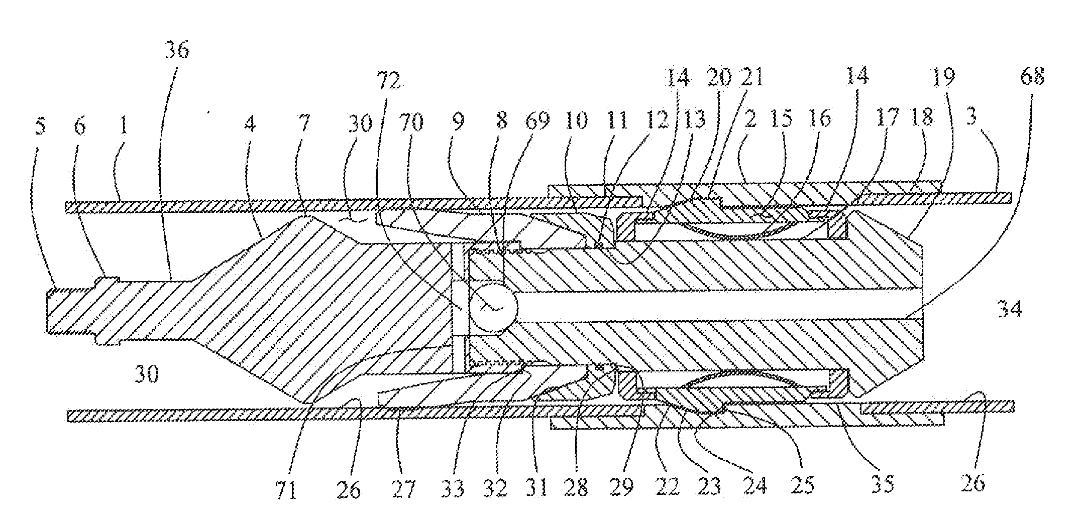
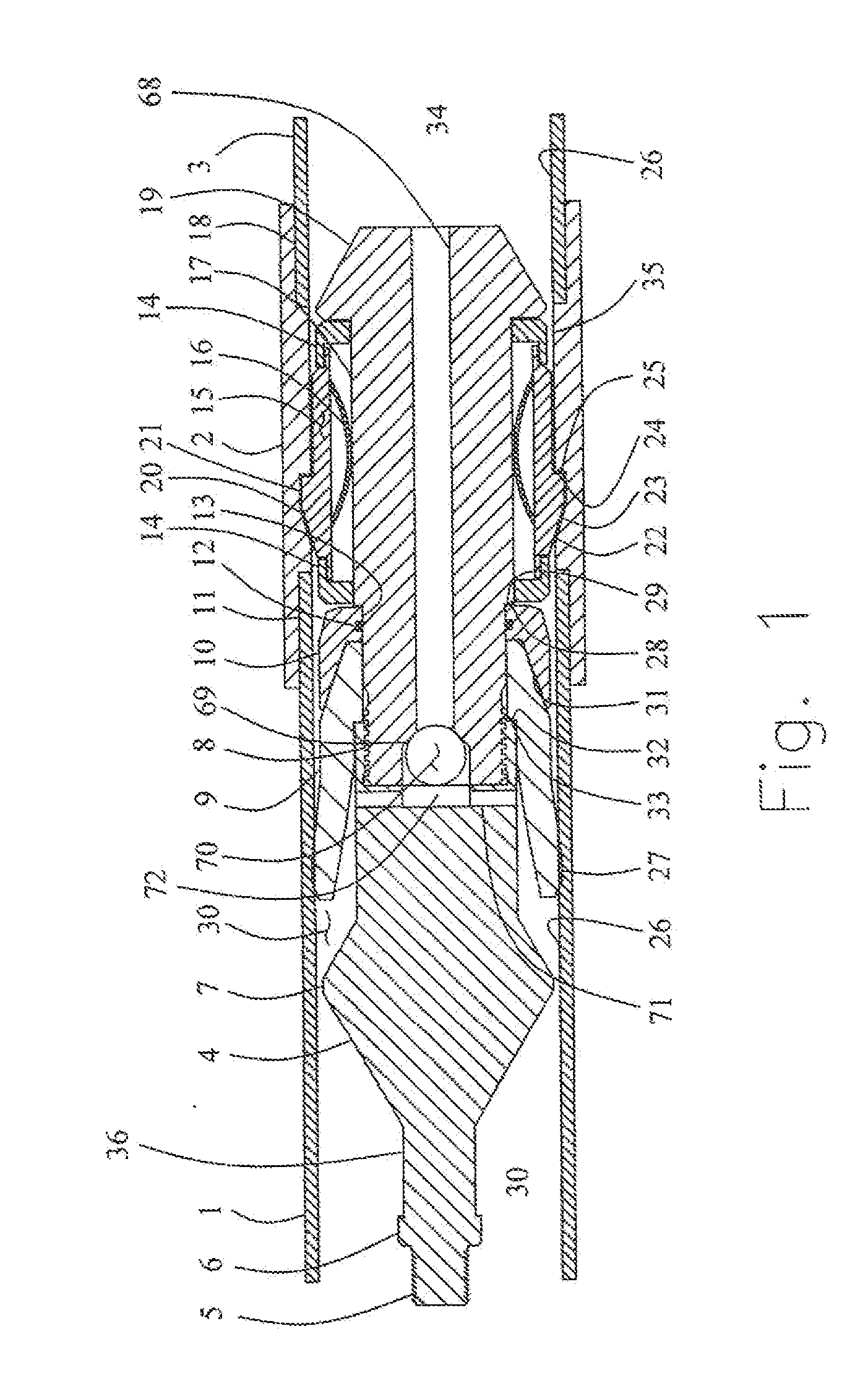
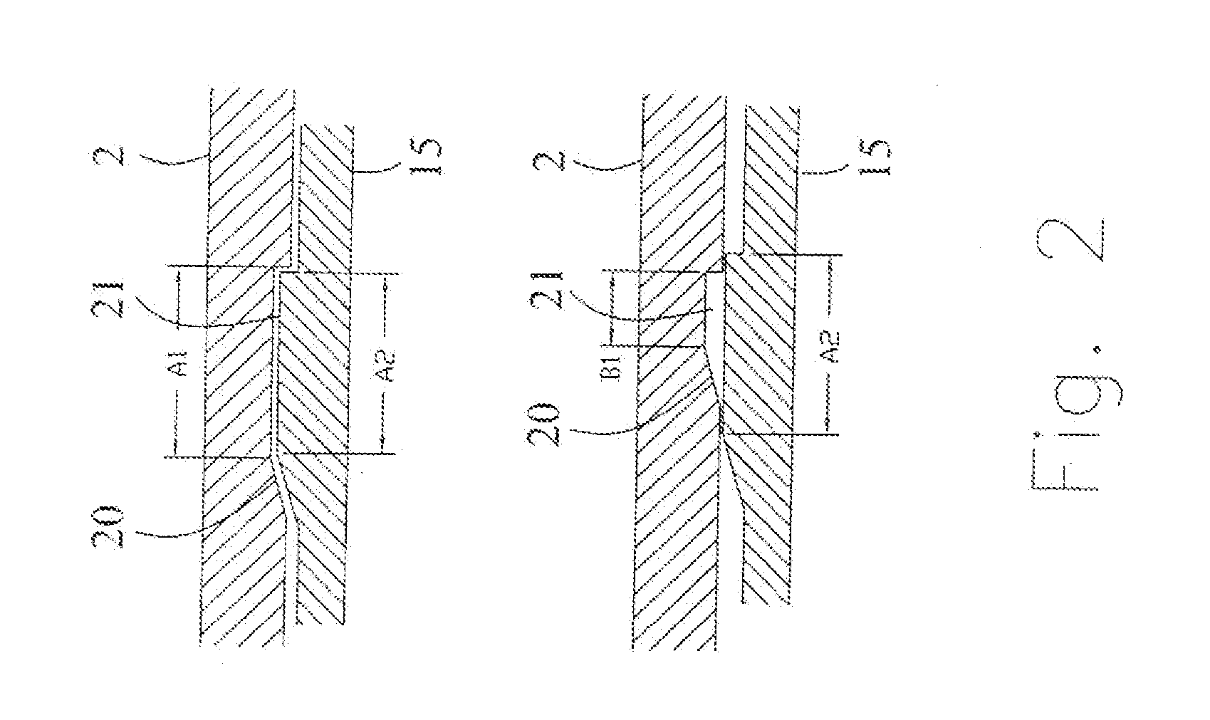
[0023]With reference to FIG. 1, the cup plug 36 is positioned inside of liner 1 which connects with liner collar 2 at thread 11, and liner 3 connects to liner collar at thread 18. Top sub 4 has standard wireline threaded connection 5 and fish neck 6, that are optional, and finned centralizer 7. Hollow pocket 72 communicates with holes 71 where holes exit under cup 9. Top sub 4 threadably connects at thread 8 to mandrel 19. Hole 68 connects to ball seat 69 where ball 70 is housed. Sealing cup 9 and thimble 10 slide over mandrel 19 over surface 13. Seal 12 seals on surface 13 and cup surface 27 seals at liner surface 26. Cup 9 prevents fluid 30 from traveling to location 34. Thimble 10 has surface 28 that shoulders against mandrel surface 29. A radial series of profile keys 15 are retained to mandrel 19 by retainer rings 14. Key profile 21 expands and matches profile 20 that is located in liner coupling 2. Springs 16 acts on surface 17 and against the inside surfaces of a series of ke...


PUM


Abstract

An array of plugging devices are pumped sequentially from the surface through a liner, that typically becomes horizontal in nature, where each plugging device is anchorable at a specified position along the length of the liner. When the plugging device is anchored, a cluster of perforations is generated above the plugging device where the perforations may be created by detonation of a perforating gun attached to the top side of the plugging device or the perforations may be created by shifting of a sleeve that is anchored to the plugging device. The plugging device may be a cup plug where the cup is similar to a swab cup and when pump pressure is applied to the cup, a force is generated to make the cup move through the liner. When anchored, the cup also directs frac fluids through the perforations to treat the well formation. The anchoring system used on the plug may be of the type where a full bore is maintained through the liner and also allows the cup plug to travel back to the surface due to flow from the well thus eliminating any need for milling obstructions from the well bore. The use of multiple plugging devices allows multizone stage fracing throughout the length of the well.

Description

[0001]This application claims priority to Provisional Application Serial No. 61 / 613,540 filed on Mar. 21, 2012.BACKGROUND OF INVENTION[0002]1. Field of the Invention[0003]The present invention relates to apparatus and methods for oil and gas wells to enhance the production of subterranean wells, either open hole, cased hole, or cemented in place and more particularly to improved multizone stimulation systems.[0004]2. Description of Related Art[0005]Wells are drilled to a depth in order to intersect a series of formations or zones in order to produce hydrocarbons from beneath the earth. Some wells are drilled horizontally through a formation and it is desired to section the wellbore in order to achieve a better stimulation along the length of the horizontal wellbore. The drilled wells are cased and cemented to a planned depth or a portion of the well is left open hole.[0006]Producing formations intersect with the well bore in order to create a flow path to the surface. Stimulation pr...

Claims


Application Information

Patent Timeline
IPC IPC(8): E21B43/26
CPCE21B43/261E21B43/26E21B43/116E21B33/1204E21B23/08E21B33/126
Inventor STOUT, GREGG W.
Owner COMPLETION TOOL DEV
Why Eureka
Try Eureka