Linear cutting stapler

a stapler and line cutting technology, applied in the field of medical instruments, can solve the problems of high cost, complicated structure, difficult manufacturing and assembly, etc., and achieve the effects of simple structure, good promotion value, and easy manufacturing

Active Publication Date: 2013-10-10
TOUCHSTONE INTERNATIONAL MEDICAL SCIENCE CO LTD
View PDF22 Cites 12 Cited by
  • Summary
  • Abstract
  • Description
  • Claims
  • Application Information

AI Technical Summary

Benefits of technology

[0008]An object of the present application is to provide a linear cutting stapler having a safety mechanism with simple structure.
[0019]The present application has main beneficial effects such as a simple structure, easy to be manufactured, safe and reliable, as well as good promotion value.

Problems solved by technology

This may cause serious consequence as arising from only cutting without stapling.
All of the above structures are complicated, and difficult to be manufactured and assembled, as well as costly.

Method used


Image

  • Linear cutting stapler
  • Linear cutting stapler
  • Linear cutting stapler

Examples


first embodiment

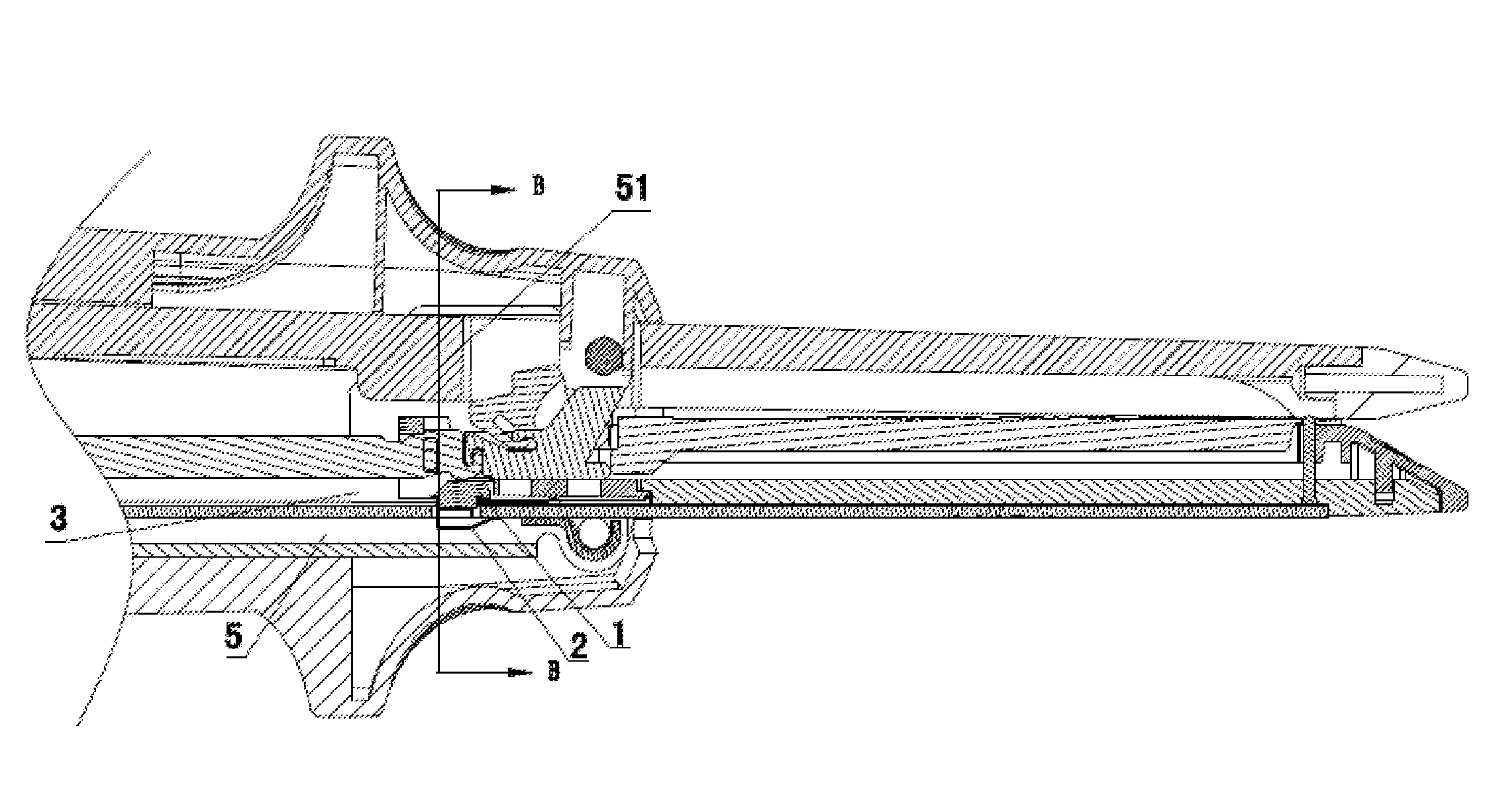
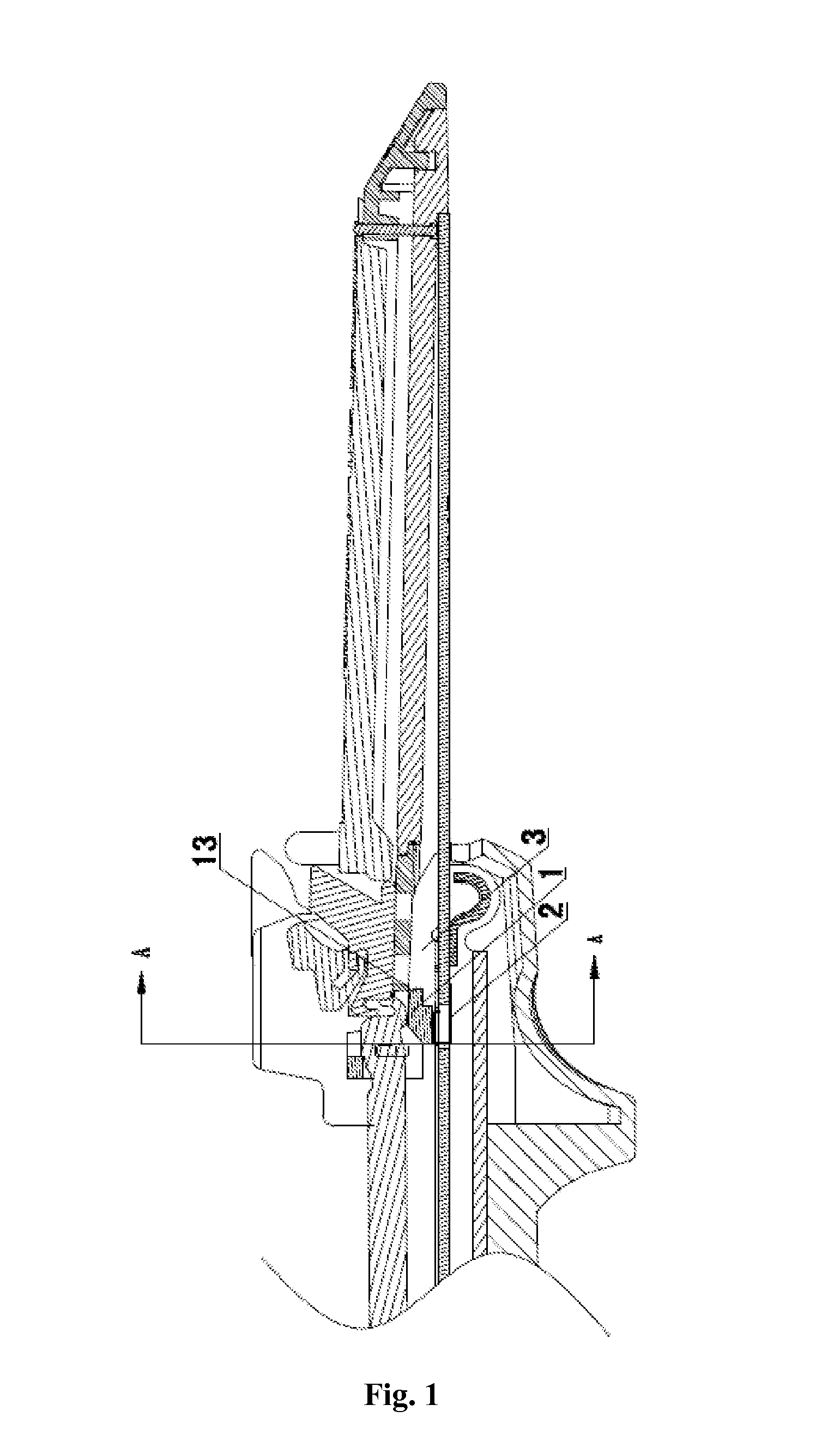
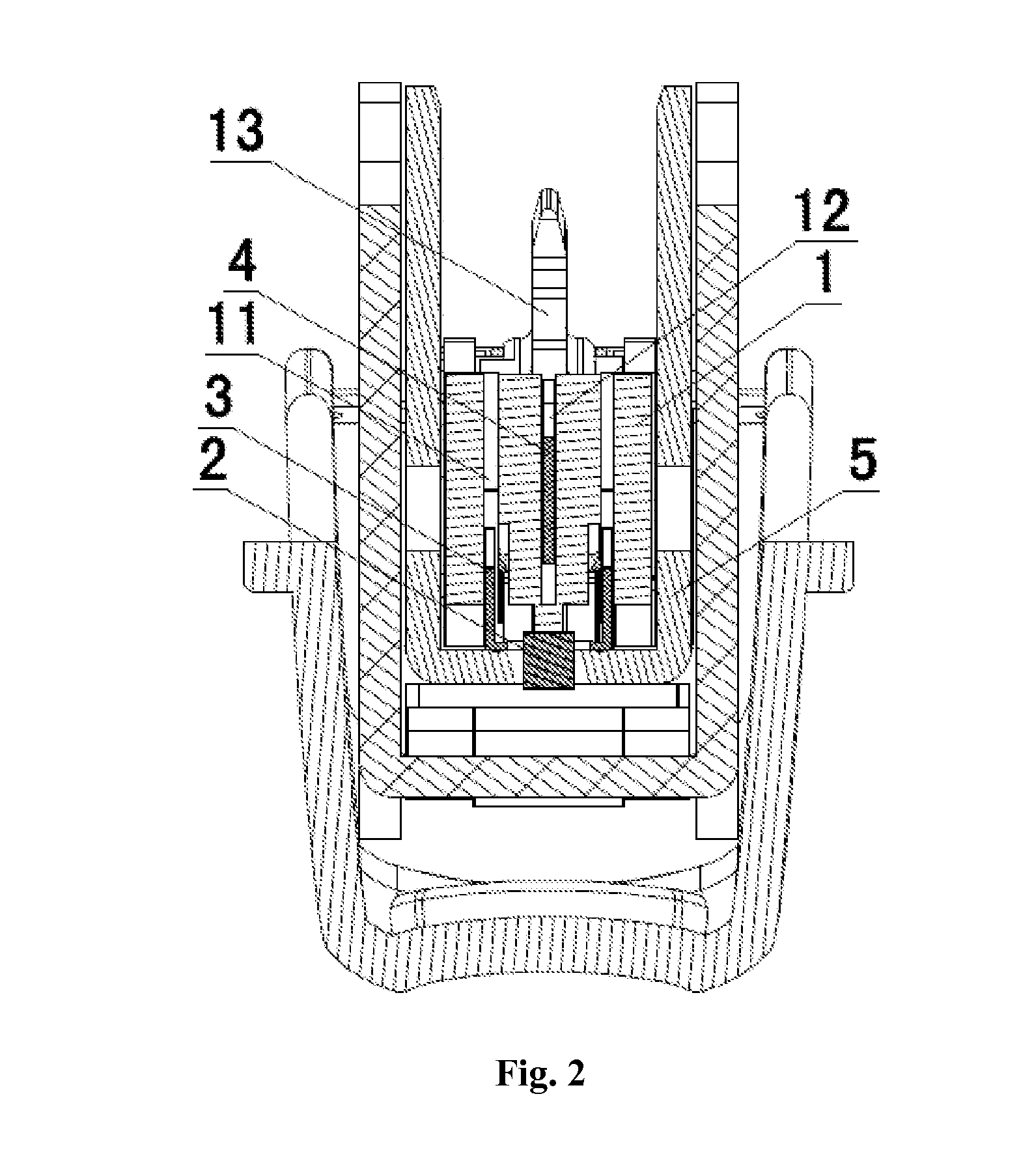
[0030]As shown in FIGS. 1 to 4, in the present application, the linear cutting stapler includes: an upper jaw, a U-shaped lower jaw 5; a staple pushing bar 3 and a cutter pushing bar 4 slidably arranged in the lower jaw 5; a safety mechanism including a leaf spring 2 and a floating block 1, with the bottom end of the leaf spring 2 being welded to the center of the inner wall of the lower jaw 5 and the floating block 1 being connected to the top end of the leaf spring 2. A first through slot 11 and a second through slot 12 for the staple pushing bar 3 and the cutter pushing bar 4 to pass through respectively are provided on the floating block 1 in an axial direction. A notch to be engaged with the top end of the leaf spring 2 is provided at the center of the bottom surface of the staple pushing bar 3. A protrusion 13 to be pressed by the staple cartridge 51 is provided at a distal end of the floating block 1. A kidney-shaped protrusion (not shown) is provided on each of the two sides...

second embodiment

[0032]As shown in FIGS. 5 to 8, in the present embodiment, the proximal end of the floating block 1 is provided with a protrusion 13 to be pressed by the staple anvil 6. Since other structures are the same as those in the first embodiment, the descriptions of those structures are not repeated here.

[0033]The principle of operation of the present embodiment is described below. When the linear cutting stapler is not opened or the staple cartridge 51 not mounted, the floating block 1 floats upwards under the action of the leaf spring 2, and then the leaf spring 2 is engaged in the notch of the bottom surface of the staple pushing bar 3, so that the staple pushing bar 3 cannot be pushed forwards, and thus the safety mechanism is activated. When the staple cartridge 51 is mounted to the lower jaw 5, and the upper jaw and the lower jaw are closed, the staple anvil 6 presses the protrusion 13, so that the floating block 1 forces the leaf spring 2 to move downwards. Then, the floating block ...

third embodiment

[0034]In the present embodiment, the engaging member is an engaging block (not shown) to be engaged with the notch. And the bottom end of the engaging block is connected to the bottom surface of the lower jaw 5 by means of a spring (not shown). The engaging block and the floating block 1 are manufactured integrally. Since other structures are the same as those in the first embodiment, the descriptions of those structures are not repeated here.

[0035]The principle of operation of the present embodiment is described below. When the linear cutting stapler is not opened or the staple cartridge 51 not mounted, the engaging block floats upwards under the action of the spring, and the floating block 1 floats upwards as well under the action of the engaging block. The top end of the engaging block is engaged in the notch of the bottom surface of the staple pushing bar 3, so that the staple pushing bar 3 cannot be pushed forwards, and thus the safety mechanism is activated. When the staple ca...


PUM

PropertyMeasurementUnit
displacementaaaaaaaaaa
elastic forceaaaaaaaaaa
U shapeaaaaaaaaaa

Abstract

A linear cutting stapler comprises: an upper jaw and a lower jaw (5) capable of closing or opening relative to each other. A staple cartridge (51) is disposed at a distal end of the lower jaw (5). The lower jaw (5) is U-shaped, and has a staple driving rod (3) and a blade driving rod (4) slidably disposed therein. The linear cutting stapler further comprises a safety mechanism. The safety mechanism comprises an engagement member. A notch fitting the engagement member is disposed on a bottom surface of the staple driving rod (3). The safety mechanism further comprises a floating block (1). The floating block (1) may perform longitudinal displacement in the lower jaw (5). When the floating block (1) is pressed against the staple cartridge (51) or an anvil (6), a top end of the engagement member is driven to perform longitudinal displacement, so that the engagement member is separated from the notch. The linear cutting stapler has a simple structure, is easy to be fabricated, and is safe and reliable.

Description

[0001]The present application claims the benefit of priority to Chinese Patent Application No. 201010592492.X titled “LINEAR CUTTING STAPLER” and filed with the State Intellectual Property Office on Dec. 16, 2010, the entire disclosure of which is incorporated herein by reference.FIELD OF THE INVENTION[0002]The present application relates to a linear cutting stapler, which belongs to the technical field of medical instruments.BACKGROUND OF THE INVENTION[0003]Linear cutting staplers are widely used in surgical operations for wound closure, and internal tissue closure and excision. A typical linear cutting stapler as disclosed in U.S. Pat. No. 5,129,570 performs two functions of stapling and cutting, to remove the redundant tissue while stapling the wound. This kind of linear cutting stapler generally includes two jaws (i.e., an upper jaw and a lower jaw), a closing handle for closing the upper jaw and the lower jaw, a staple anvil and a staple cartridge arranged opposite to each othe...

Claims


Application Information

Patent Timeline
Patent Type & Authority Applications(United States)
IPC IPC(8): A61B17/072
CPCA61B17/07207A61B2017/07285A61B19/30A61B17/072A61B2017/07278A61B90/03
Inventor CHEN, WANGDONGFU, KAIFENZHOU, JING
Owner TOUCHSTONE INTERNATIONAL MEDICAL SCIENCE CO LTD
Why Eureka
Try Eureka