Pin miller inserts and a cutter using same

a technology of milling cutter and milling insert, which is applied in the direction of shaping cutter, attachable milling devices, manufacturing tools, etc., can solve the problems of difficult to achieve positive axial rake angle, difficult to provide large dish angle, etc., to achieve enhanced main cutting edge strength, stable clamping in the pocket, and the effect of reducing the contact resistance of the workpiece during machining

Active Publication Date: 2013-10-10
TAEGUTEC
View PDF6 Cites 10 Cited by
  • Summary
  • Abstract
  • Description
  • Claims
  • Application Information

AI Technical Summary

Benefits of technology

[0007]The present disclosure aims to provide a pin miller insert and a milling cutter allowing a large dish angle so as to minimize the contact resistance while machining crank shafts.
[0008]This invention aims also to enhance the strength of the main cutting edges of the insert and make its clamping screw durable.
[0013]Since the insert according to this disclosure when mounted on a milling cutter allows an inclined orientation, the side faces of the inserts can make a dish angle so as to minimize the contact resistance to the work-piece during machining. Since the main cutting edges have a negative rake angle, strength of the main cutting edges is enhanced. The insert according to this disclosure has the structure making its clamping screws durable. Also, the insert according to this disclosure allows a stable clamping in the pocket and is secured by maintaining a constant contact area against the pocket side wall.

Problems solved by technology

In this case, error proofing in manufacturing is difficult and a positive axial rake angle is hard to be achieved.
Since a parallelogrammic type insert such as disclosed in U.S. Pat. No. 6,764,254 has a rectangular rake face, it does not provide a large dish angle.

Method used


Image

  • Pin miller inserts and a cutter using same
  • Pin miller inserts and a cutter using same
  • Pin miller inserts and a cutter using same

Examples


Embodiment Construction

[0021]Hereinafter, detailed embodiments according to the present disclosure are described. However, the present invention can be realized in other various forms, and is not limited to the embodiments explained herein. The figures attached to the present disclosure are merely for convenience of explanation, and the shapes and the relative scales may be exaggerated or distorted. Some portions of the figures which are not necessary for explaining the features of the present invention may be abridged for clearer explanation of the invention.

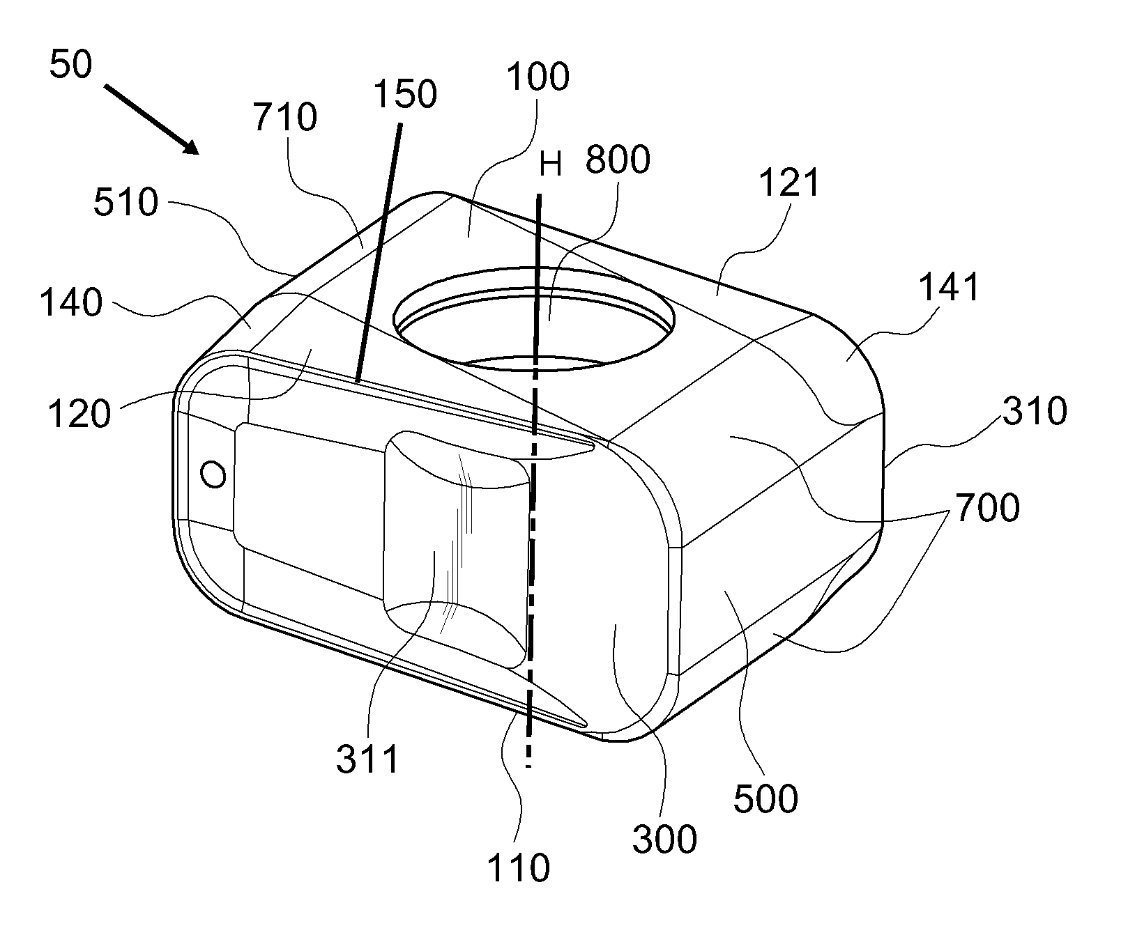
[0022]FIG. 1 is a perspective view of a pin miller insert 50 in accordance with the present disclosure. This insert is mountable on a crank pin milling cutter.

[0023]As shown in FIG. 1, the insert has a hexahedral shape having an opposed pair of top and bottom abutting faces 100,110, an opposed pair of rake faces 300,310, and an opposed pair of side faces 500,510 with a central hole 800 having axis H passing through each central portion of the abuttin...


PUM

PropertyMeasurementUnit
widthaaaaaaaaaa
radiusaaaaaaaaaa
angleaaaaaaaaaa

Abstract

An indexable hexahedral cutting insert has opposing top and bottom abutting faces, opposing rake faces connecting to opposing side faces, and a central hole passing through the abutting faces. Each rake face is wider in the top-to-bottom direction at a different one of the side faces. Arcuate corner portions with one-directional curvature are formed along intersecting portions between the abutting faces and the side faces. Each abutting face has first and second wedge-shaped inclined planes adjoining and inclining toward corresponding first and second rake faces. Each inclined plane has a base side at a cutting edge formed at the border with one of the rake faces, and a width which gradually increases from one corner portion to the opposite corner portion along the abutting face. Each corner portion has an associated inclined arcuate surface adjacent to the wide end of the wedge-shaped inclined planes.

Description

RELATED APPLICATIONS[0001]This is a Continuation-in-Part of International Application No. PCT / KR2011 / 005710, filed 3Aug. 2011 and published as WO 2012 / 036379A2, which claims priority to KR 10-2010-0091981, filed 17 Sep. 2010. The contents of the aforementioned applications are incorporated by reference in their entiretyFIELD OF THE INVENTION[0002]This disclosure is related to a pin miller insert and a milling cutter using the same.BACKGROUND[0003]In roughing the pin or journal parts of crank shafts which are generally steel, the depth of cut is large, a large dish angle is required to minimize the contact on the work-piece, and cutting edges are required to be strong as well.[0004]Conventionally, there have been two types of inserts applied for the purpose of crank shaft machining: one is rectangular type or the other is parallelogrammic type.[0005]A rectangular type insert has a parallelogrammic rake face to allow a large dish angle for decreasing the contact on the work-piece. In ...

Claims


Application Information

Patent Timeline
Patent Type & Authority Applications(United States)
IPC IPC(8): B23C5/00
CPCB23C3/06B23C5/08B23C5/207B23C2200/085B23C2200/125Y10T409/30952B23C2200/367B23C2210/503B23C2220/68B23C5/006Y10T407/23B23C2200/283B23C5/202
Inventor LEE, YOUNG HO
Owner TAEGUTEC
Why Eureka
Try Eureka