Silent chain

a technology of silent chain and guide plate, applied in the direction of driving chain, belt/chain/gearring, chain elements, etc., can solve the problems of generating an unpleasant explosive sound when released, reducing the fatigue strength of the chain as a whole, and reducing the weight of the guide plate. , to achieve the effect of suppressing bending or bowing of the connecting pin, reducing the weight of the guide plate, and avoiding galling on the surfa

Inactive Publication Date: 2013-10-10
TSUBAKIMOTO CHAIN CO
View PDF3 Cites 8 Cited by
  • Summary
  • Abstract
  • Description
  • Claims
  • Application Information

AI Technical Summary

Benefits of technology

[0013]One advantage of the invention is that the cut-away portions reduce the weight of the guide plate. The cut-out portions also allow the guide plate to elongate elastically in the longitudinal direction of the chain, and the guide plate thus follows the movements of the link plates constituting the guide rows and the non-guide rows pins. Consequently, it becomes possible to suppress bending or bowing of the connecting pins and to avoid galling on the surfaces of the connecting pins, and also to prevent the tensile loads acting on the link plates and guide plates from becoming unbalanced. Thus it is possible to reduce elongation of the chain due to wear, to increase the fatigue strength of the chain, and extend the useful life of the chain.
[0014]The longitudinally offset relationship of the cut-away portions of the guide plate also prevents the cross-sectional area of the guide plate from decreasing sharply even when the cut-away portions are large. Thus, it is possible to facilitate elastic elongation of the guide plate by increasing the size of the cut-away portions on the inner and outer sides and thereby avoid uneven wear on the surfaces of the connecting pins contacted by the link plates. The increased elastic elongation of the guide plate occurs both at the inside cut-away portion and the outside cut-away portion of the guide plate. Consequently it is possible to achieve improved suppression of bending or bowing of the connecting pins in the longitudinal direction of the chain. Uneven wear, i.e., galling, of the connecting pins is avoided and the tensile load on the link plates of the chain is prevented from becoming unbalanced.
[0015]Furthermore, because cut-away portions are formed on the inner sides of the guide plates, when the link plates of a guide row engage a sprocket, the air confined between the teeth of the link plates and the sprocket teeth freely escapes in a lateral direction through the cut-away portions on the inner sides of the guide plates. Thus, it is possible to reduce noise to a level below the level of the noise generated by confinement and compression of air between the link plate teeth and sprocket teeth in a conventional silent chain.
[0016]According to a second aspect of the invention, the deepest parts of the cut-away portions of each guide plate are disposed on opposite sides of a portion of the pitch line of the same guide plate between centers of the pin holes thereof. Each of the deepest parts of the cut-away portions of each guide plate can be disposed on an imaginary line perpendicular to the pitch line and between the centers of the pin holes thereof. The deepest part of each of the cut-away portions of each guide plate can be disposed on an imaginary line perpendicular to the pitch line and intersecting the pitch line between the pin holes. This positioning of the cut-away portions allows the guide plates to have external dimensions that enable them to engage the sides of sprocket teeth while the teeth of the guide rows and the non-guide rows sequentially engage sprocket teeth and thereby prevent the guide rows and the non-guide rows from sliding laterally.
[0017]According to a third aspect of the invention, the inner side of a guide plate has outer flanks, and the shortest distance A from the cut-away portion on the outer side of each guide plate to the nearest of the pin holes thereof, the shortest distance B from a pin hole thereof to the part of the back surface farthest from the pitch line, the shortest distance C from an outer flank on the inner side to the nearest of the pin holes thereof, and the shortest distance D from one of the cut-away portions to the other satisfy the relationships
[0018]With the above relationships, the cut-away portion can allow increased elastic deformation of the guide plate in the longitudinal direction when the chain is under tensile stress while maintaining the tensile strength of the plate at a level substantially the same as that of a conventional guide plate.

Problems solved by technology

Consequently, the outermost link plates more easily undergo abrasive wear and or more subject to the formation of cracks, and the fatigue strength of the chain as a whole decreases.
Air confined in this space is compressed and generates an unpleasant explosive sound when released.
Here again, uneven wear causes galling of the surfaces of the connecting pins where they contact the pin holes.

Method used


Image

  • Silent chain
  • Silent chain
  • Silent chain

Examples


first embodiment

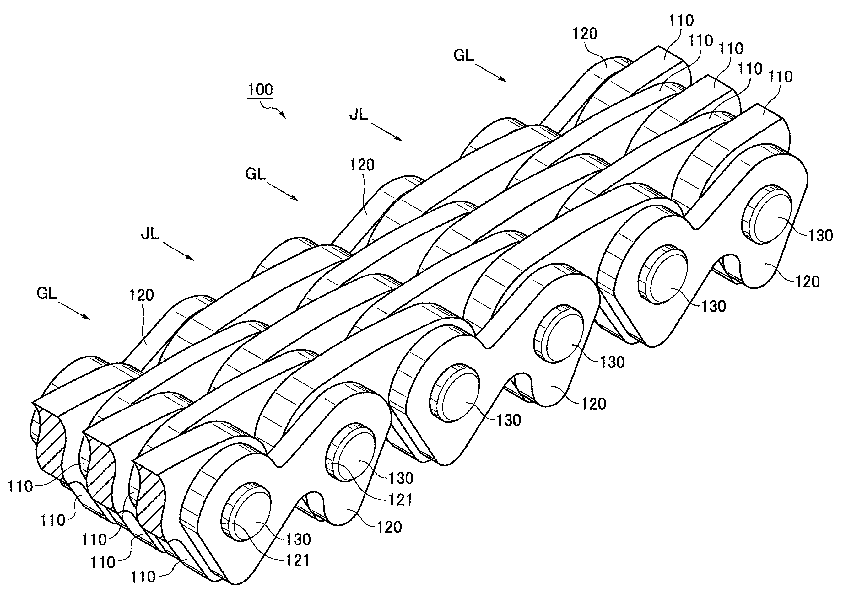
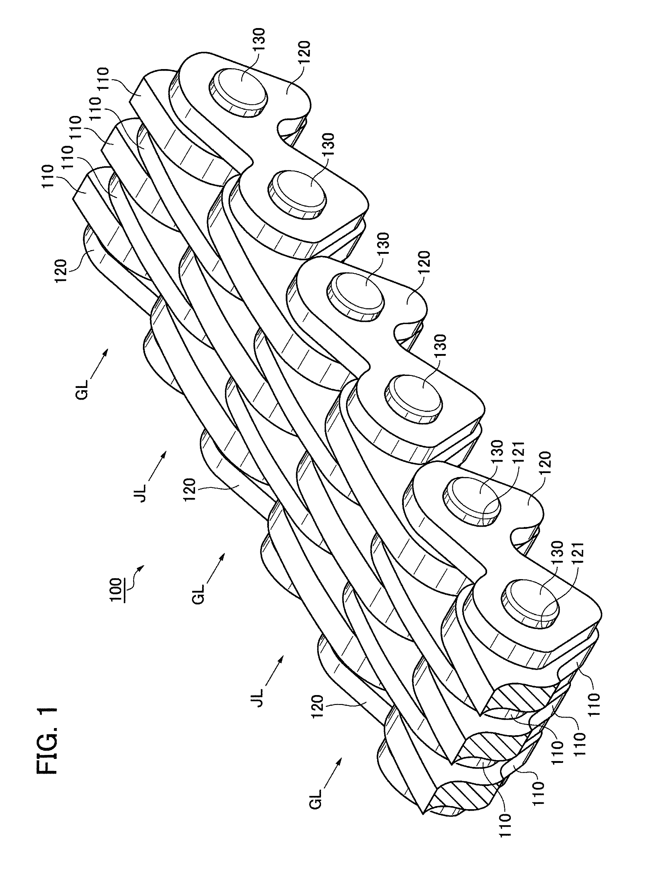
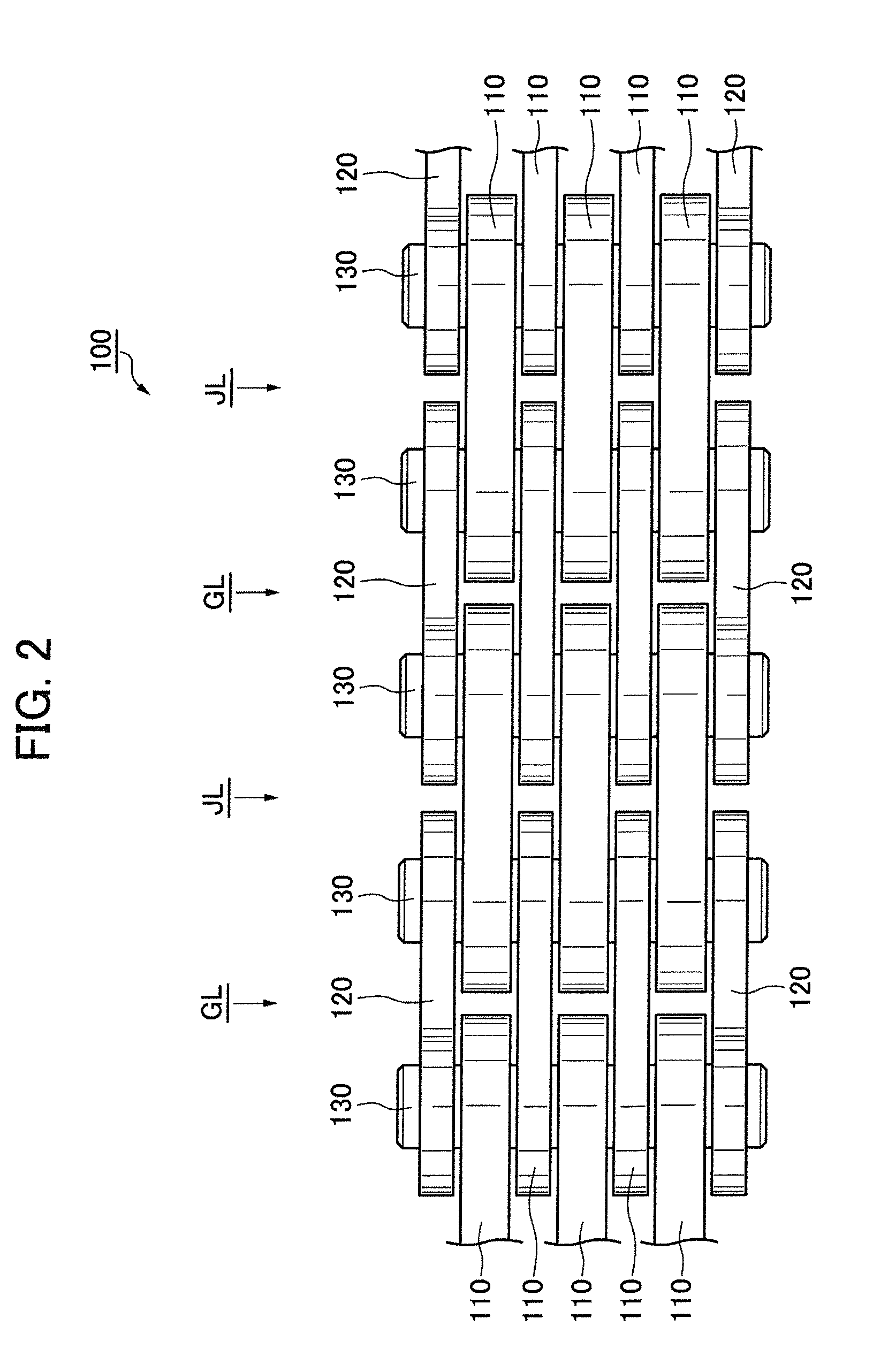
[0038]As shown in FIGS. 1 and 2, a silent chain 100 according to the invention includes link plates 110 arranged in guide rows GL and non-guide rows JL. The guide rows and non-guide rows are arranged in alternating relationship along the longitudinal direction of the chain so that the chain is in the form of an endless loop. A pair of guide plates 120, each having a pair of pin holes 121 is provided on each guide row GL, one guide plate being at each end of the guide row so that link plates of the guide row are disposed between the two guide plates. Each of the link plates 110 has two pin holes through which connecting pins 130 fit loosely to connect the plates of the guide rows and non-guide rows in interleaved relationship. The connecting pins are press-fit into the pin holes 121 of the guide plates 120.

[0039]In a transmission, for example an engine timing drive, the silent chain 100 is engaged with driving and driven sprockets (not shown) so that a side of the link plates 110 tha...

second embodiment

[0053]In a second embodiment, shown in FIGS. 8 and 9, a guide plate 220 has a cut-away portion 222 on its inner side and a cut-away portion 223 on its outer side. The shape of each of these cut-away portions consists entirely of a plurality of curved lines. The curved shapes of the cut-away portions of the guide plate in FIGS. 8 and 9 provides improved suppression of the generation of cracks at the cut-away portions.

third embodiment

[0054]In a third embodiment, shown in FIGS. 10 and 11, the cut-away portion 323 of the back surface on the outer side of guide plate 320 includes a flat surface. In this embodiment, the strength of the part of the plate 320 between the cut-away portion 323 and the hole 321 farthest from the flat surface is increased. This configuration suppresses the generation of cracks in the vicinity of a deepest point 323a of the cut-away portion 323 on the outer side of the plate.

[0055]Various modifications can be made to the embodiments described above.

[0056]For example, whereas the connecting pins 130 shown in FIG. 1 are round pins, the connecting pins of the chain in accordance with the invention can be rocker joint pins each consisting of a rocker pin and a joint pin. When a round pin is used, it tends to contact the inner surface of the pin hole of the link plate in a parallel fashion over a larger area without applying a biased load, so that wear is reduced and wear elongation of the chai...


PUM


Abstract

A silent chain includes guide plates each of which has a cut-away portion on its inner side and a cut-away portion on its outer side for allowing elastic deformation of the guide plate in the longitudinal direction of the chain so that bowing of the connecting pins of the chain is reduced, and galling of the connecting pins and unbalance of the loads on the link plates of the chain are suppressed. The deepest parts of the respective cut-away portions are longitudinally offset from each other so that longitudinal elastic deformation can occur without impairing the tensile strength of the guide plate.

Description

CROSS-REFERENCE TO RELATED APPLICATION[0001]The disclosure of Japanese patent application 2012-085615, filed on Apr. 4, 2012 is incorporated herein by reference.FIELD OF THE INVENTION[0002]The invention relates to a silent chain of the kind used in the timing system of an internal combustion engine, and particularly to a silent chain which allows guide plates to deform elastically in a longitudinal direction.BACKGROUND OF THE INVENTION[0003]In a conventional silent chain, link plates having pairs of pin holes are arranged alternately in guide rows and non-guide rows with the link plates of each row interleaved with link plates of a preceding row and a following row to provide a chain in the form of an endless loop. The rows of link plates are connected by pins that extend through the pin holes in the link plates. Guide plates are arranged at both ends of each guide row and the pins are press-fit into pin holes of the guide plates but fit loosely in the pin holes of the other plates ...

Claims


Application Information

Patent Timeline
Patent Type & Authority Applications(United States)
IPC IPC(8): F16G13/04
CPCF16G13/04
Inventor MOTOSHIMA, YOSHIKISONODA, MASATOSHIOKADA, NAOKITSUJINO, YOSHINORI
Owner TSUBAKIMOTO CHAIN CO
Why Eureka
Try Eureka