Actuated leg prostheses for amputees

a joint mechanism and amputee technology, applied in the field of joint actuation mechanism, can solve the problems of affecting the autonomy of the device, affecting the weight of the device, affecting the weight and size of the device, etc., and achieve the effect of reducing the power consumption of the joint actuation mechanism, efficient mechanical energy return, and less efficien

Active Publication Date: 2013-10-10
NATIONAL BANK OF CANADA
View PDF9 Cites 33 Cited by
  • Summary
  • Abstract
  • Description
  • Claims
  • Application Information

AI Technical Summary

Benefits of technology

The invention is a knee actuation mechanism for prosthetic devices and orthotic devices that restores the natural dynamics and enables common activities such as walking and sitting. It also reduces energy consumption by storing and efficiently returning mechanical energy. The compliant transmission mechanism increases the autonomy of the device, reduces the dimensions and weight of the battery pack, and reduces noise-generating vibrations. The angular deflection of the compliant transmission is measured in real-time by a rotational sensor to provide a smoother motion and better adapt to the user's gait style. The mechanical compliance also contributes in improving the comfort of the device. Overall, the invention provides a more efficient and comfortable prosthetic or orthotic device.

Problems solved by technology

A drawback of known joint actuation mechanisms include important electrical energy input to operate, affecting the autonomy of the device and requiring, important battery capacity thereby affecting the weight of the device.
Another drawback of know joint actuation mechanisms is that they are heavy and voluminous, directly affecting the weight and size of the device.
Some drawbacks of known knee actuation mechanisms is that they do not provide real-time direct measurement of the torque and do not demonstrate compliance in any locomotion situation, consequently the prosthetic or orthotic device to which they are mounted does not smoothly respond to the commands of a user, to unexpected events nor does it easily adapt to the specific gait style of a user.
Still another drawback of conventional powered joint actuation mechanisms is that they are relatively noisy as causing embarrassment to the user in relatively quiet social settings.

Method used


Image

  • Actuated leg prostheses for amputees
  • Actuated leg prostheses for amputees
  • Actuated leg prostheses for amputees

Examples


Embodiment Construction

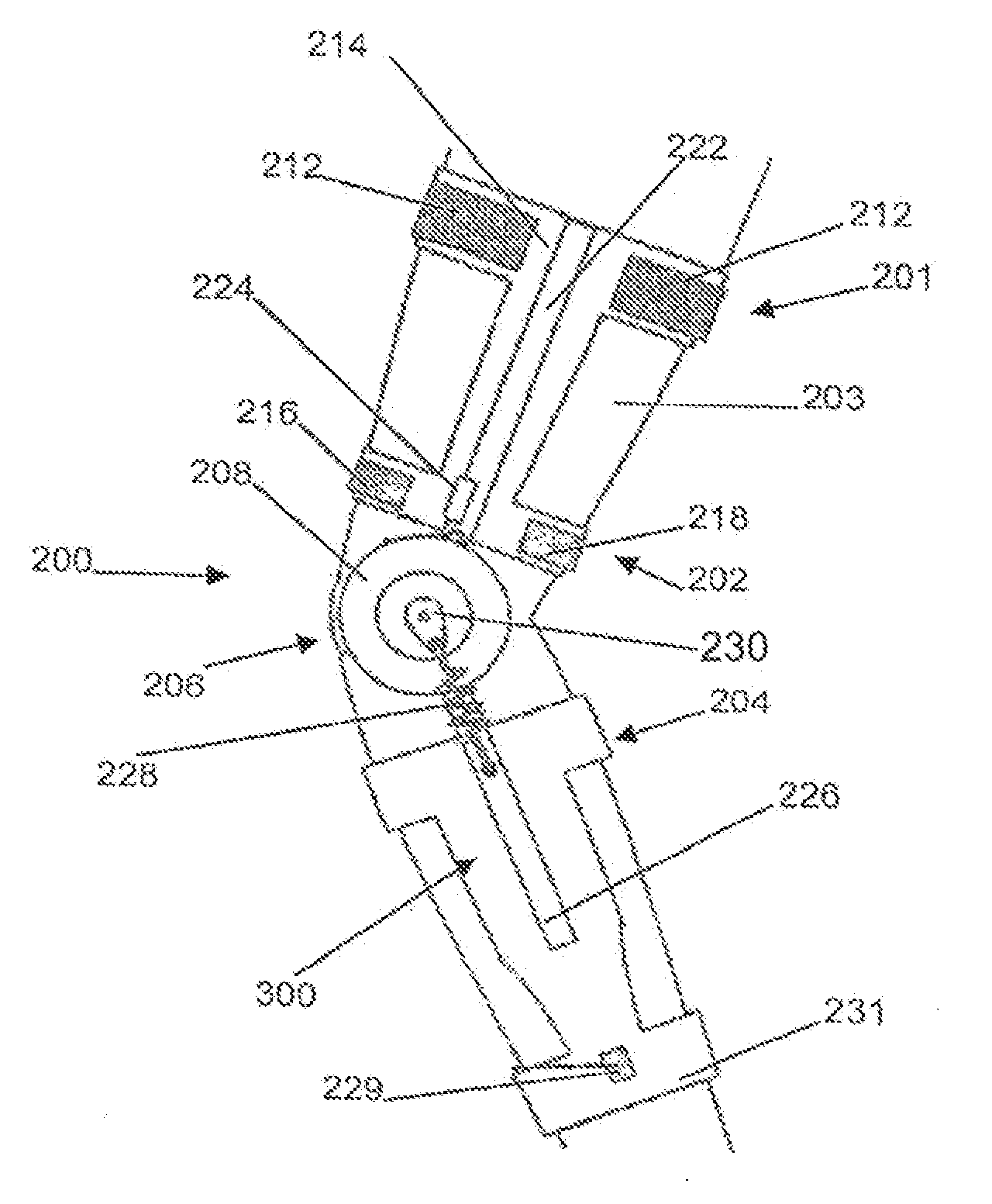
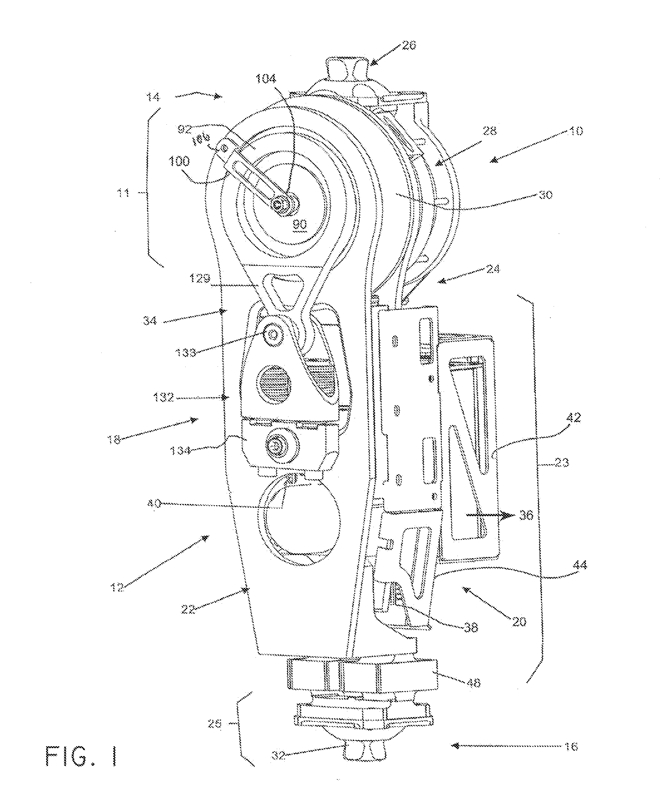
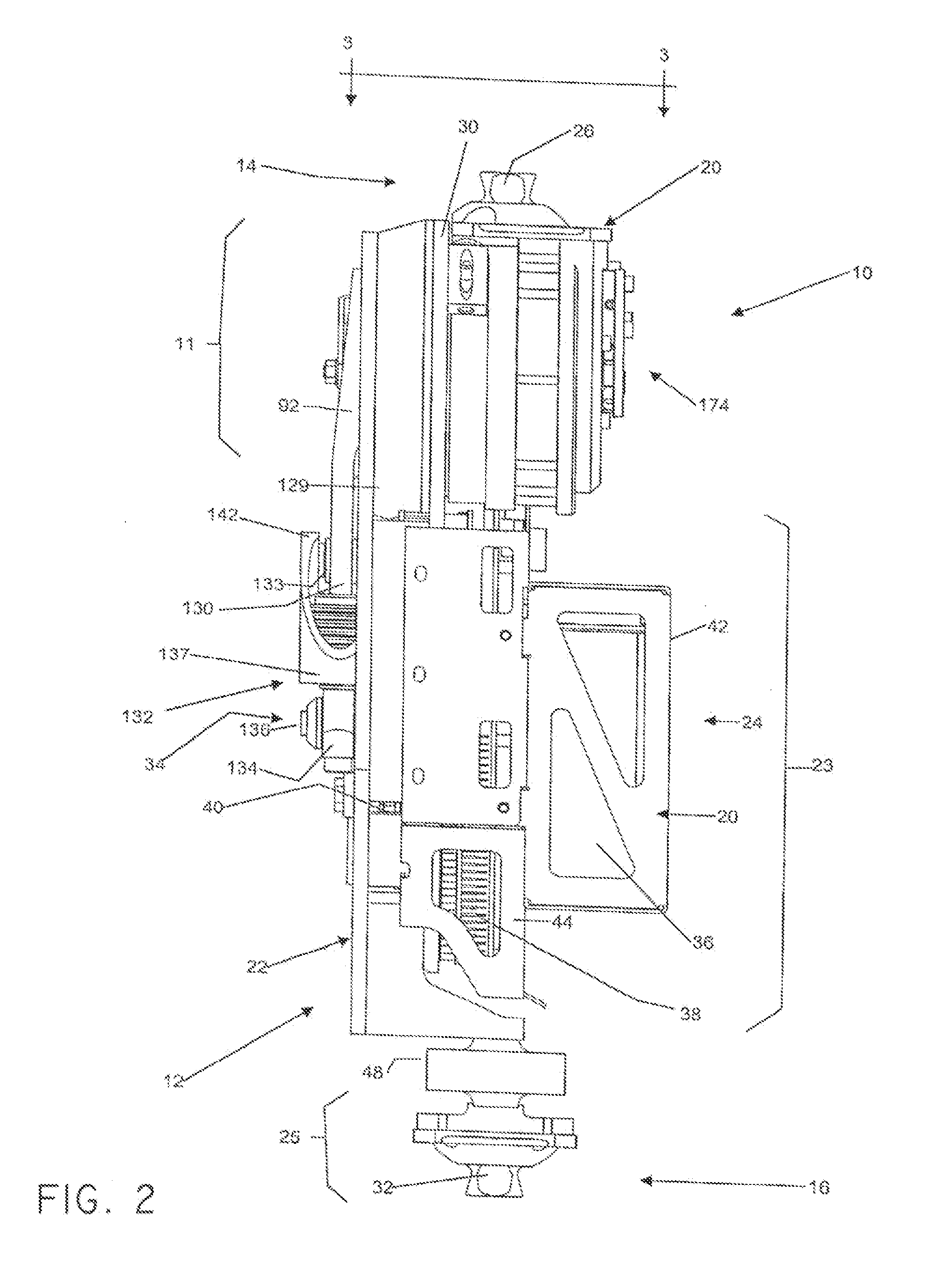
[0063]Generally stated, the present invention relates to a prosthetic / orthotic device having at least one device portion (prosthetic or orthotic portion) and joint portion. The joint portion provides for the at least one device portion to pivot between flexion and extension movements relative to another adjacent device portion or an adjacent limb segment (such as a stump) of the user. The device includes a compliant transmission assembly in operational communication with the joint portion. The compliant transmission assembly comprises a compliant member and a pivot interposed between this compliant member and the joint portion. The compliant member absorbs energy during flexion and releases this energy during extension. When absorbing energy, the compliant member dampens flexion and when releasing energy, compliant member assists extension.

[0064]With reference to the appended drawings illustrative embodiments of the present invention will now be described so as to exemplify the inve...


PUM


Abstract

A prosthetic or orthotic device can include at least one device portion and a joint portion for providing for the at least one device portion to pivot between flexion and extension movements relative to another adjacent device portion or an adjacent limb segment of a user. In some embodiments, a prosthetic or orthotic device can include a compliant transmission assembly in operational communication with the joint portion. The compliant transmission assembly can include a compliant member and a pivot. The pivot can be interposed between the compliant member and the joint portion. In some embodiments, the compliant member absorbs energy when a torque is applied.

Description

FIELD OF THE INVENTION[0001]The present invention relates to a joint mechanism for a prosthetic and / or orthotic device. More particularly, but not exclusively the present invention relates to a joint actuation mechanism for a prosthetic and / or orthotic device having a compliant transmission.BACKGROUND OF THE INVENTION[0002]A few types of joint actuation mechanisms for prosthetic or orthotic devices are known in the art and include joint actuation mechanisms. Usually, powered joint mechanisms form part of an orthotic device or a prosthetic device and include a housing for an actuator comprising a motor and a shaft in communication with a reducer which communicates with an output to cause the joint to rotate about an axis thereof.[0003]A drawback of known joint actuation mechanisms include important electrical energy input to operate, affecting the autonomy of the device and requiring, important battery capacity thereby affecting the weight of the device. Another drawback of know join...

Claims


Application Information

Patent Timeline
Patent Type & Authority Applications(United States)
IPC IPC(8): A61F2/64
CPCA61F2/582H02K11/0042A61F2/64A61F2/68A61F2/76A61F5/0125A61F2002/30359A61F2002/30446A61F2002/30523A61F2002/5003A61F2002/5004A61F2002/5009A61F2002/503A61F2002/5041A61F2002/5043A61F2002/5069A61F2002/5072A61F2002/5075A61F2002/6854A61F2002/701A61F2002/704A61F2002/741A61F2002/745A61F2002/747A61F2002/7625A61F2002/764A61F2002/7645A61F2005/0169A61F2005/0179A61F2220/0025A61F2220/0033A61F2220/0041G01L3/1421H02K7/116A61F2/605A61F2/70A61F5/0123A61F2002/30433A61F2/74A61F2/741H02K11/24A61F2005/0137
Inventor GILBERT, BENOITLANDRY, DAVID
Owner NATIONAL BANK OF CANADA
Why Eureka
Try Eureka