Method, system, and apparatus for aiming LED lighting

Inactive Publication Date: 2013-10-10
MUSCO
View PDF2 Cites 31 Cited by
  • Summary
  • Abstract
  • Description
  • Claims
  • Application Information

AI Technical Summary

Benefits of technology

[0025]Other embodiments facilitate demonstrating lighting techniques and applications by reducing the amount of time spent at

Problems solved by technology

There is a vast number of available options in lighting (e.g. types of light sources, types of optics, color, color temperature, intensity, efficiency, etc.) and a wide variety of potential applications of illumination schemes for different applications; this presents complexities to lighting designers, manufacturers and installers.
In the second case particularly, the customer typically does not have sufficient knowledge of lighting to be able to provide measurable specifications.
The result may be an inability to communicate what is desired to the designer such that the customer can only say “I'll know it when I see it.”
However during design or installation it may become apparent that lighting sources that exactly meet the desired specifications may not be available.
Likewise it may become apparent that ambient conditions may be actually different than described because of error or because of a physical change in the target area.
Thus considerable effort may be s

Method used


Image

  • Method, system, and apparatus for aiming LED lighting
  • Method, system, and apparatus for aiming LED lighting
  • Method, system, and apparatus for aiming LED lighting

Examples


first embodiment

[0039]One embodiment according to aspects of the invention uses point-by-point analysis to provide aiming points for fixtures. The result of this analysis is the ability to identify points on a target area such as a field, lot, or building, which can be used as targets for aiming fixtures. Frequent reference should be taken to FIGS. 7A and B. This example, illustrated through FIGS. 7A and B, pertains to an illumination task for buildings and other objects on a property. The FIGS. 7A and B show an image that could be displayed on screen 650 of, for example, a digital camera, or some display associated with a computer (laptop, PDA, smart phone, desktop, etc.). However, in this example, the methodology is applied to the physical property in the following way.

[0040]An efficient way to set up a demonstration of lighting or install lighting for illuminating the house, the trees to the right of the house, and the statue to the left of the house, would be to establish in real space aiming p...

second embodiment

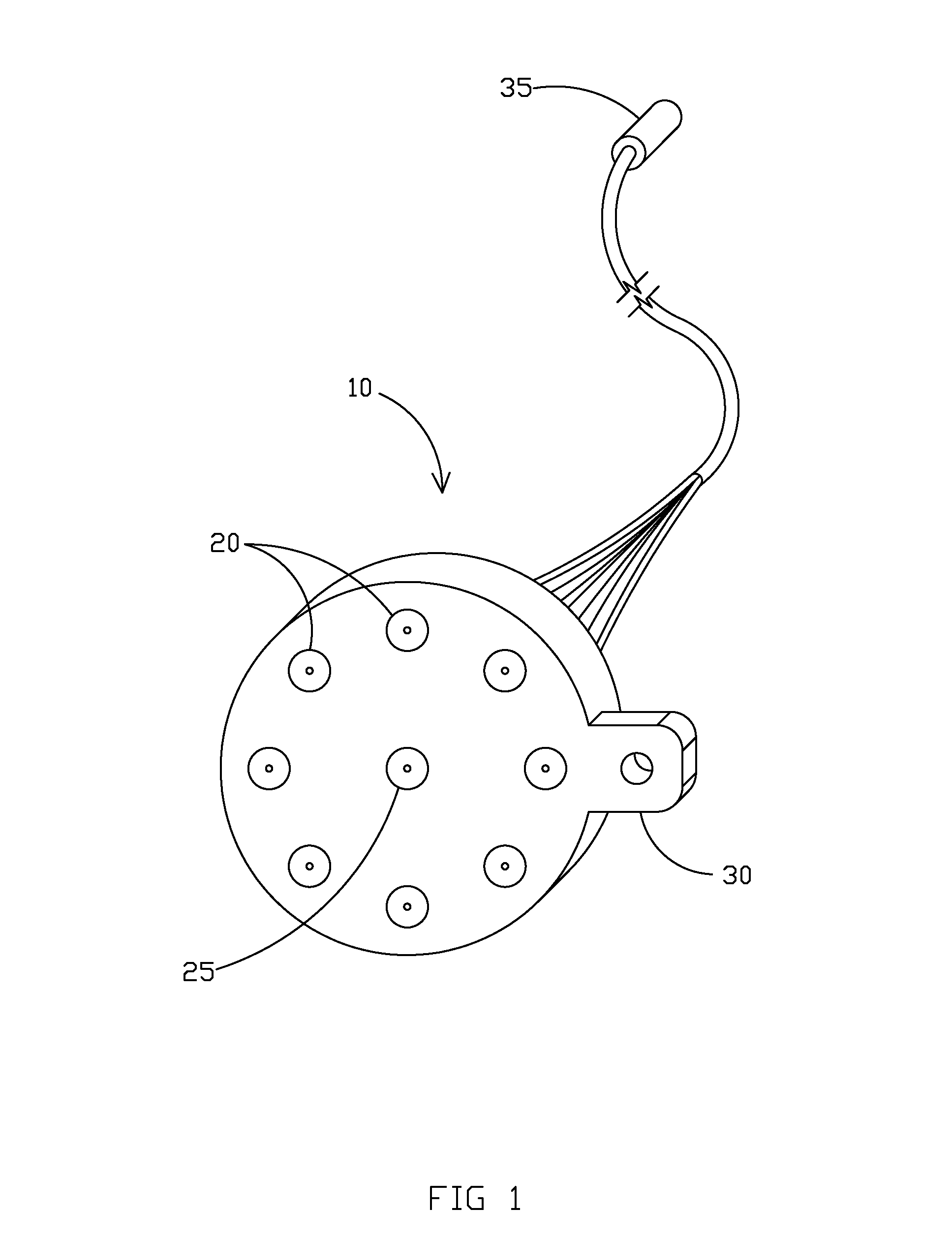
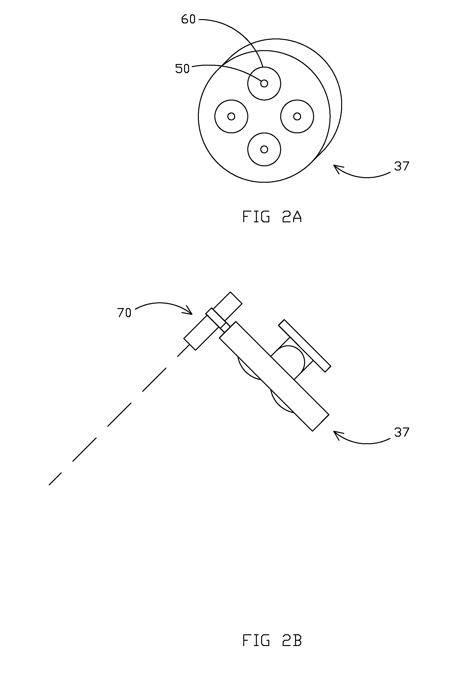
[0055]Variation on the concept of helping define aiming points or assisting in characterizing how lighting would actually apply to a given lighting task are illustrated in FIGS. 1, 2A-G, and 3A-E. Instead of utilizing some reference points with range and azimuth measurement capabilities to then record a description of aiming points or other locations at the physical target, the embodiments of FIGS. 1, 2A-G, and 3A-E utilize one or more laser beams that would project from either a demonstration location, tentative installation location, or permanent installation location for a light fixture to the actual target. Among other things, the lasers can be used to assist in several useful procedures. The procedures include, but are not limited to: visualizing how a fixture's light beam would place on the target; aiming (either from the aiming location for the fixture or from the fixture itself to the target), or helping characterize the light beam pattern on the target.

[0056]In these exampl...

third embodiment

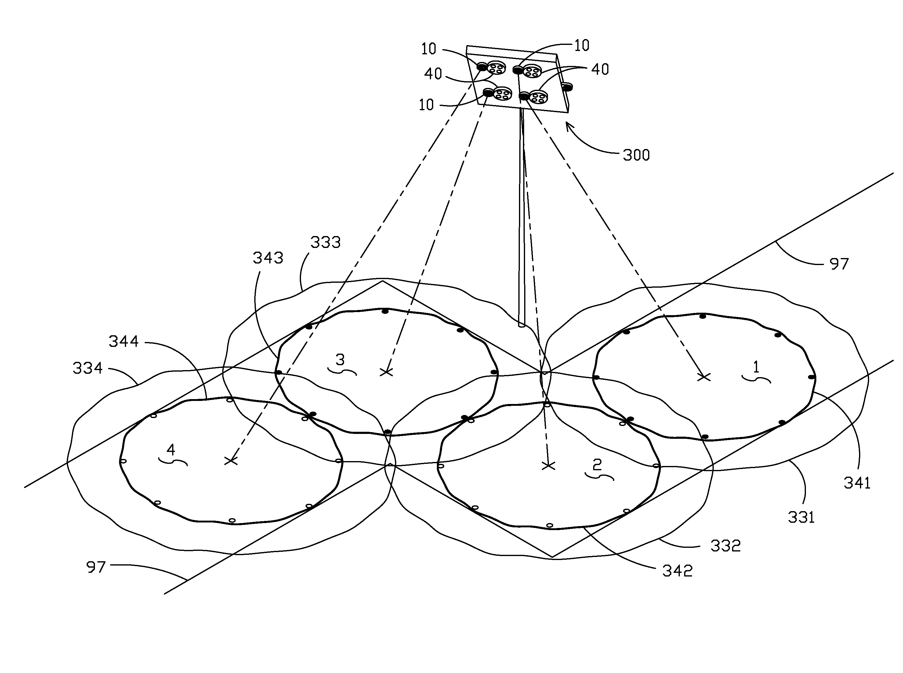
[0075]Another embodiment according to aspects of the invention uses multiple light sources 40 installed in a fixture 300, FIG. 3A. Laser arrays 10 could be installed on at least some of the light sources 40 and could be permanently or removably installed. Light sources 40 could be pre-aimed with reference to the entire fixture 300 such that the fixture would have a known beam pattern. Such beam pattern could be represented by the output from laser array 310. Aiming laser 370 could be included to allow laser array 310 to be aimed coaxially with the fixture. In this configuration, the fixture 300 would function identically to the previously described light sources 40 represented in FIG. 2D-2G. FIG. 3B shows fixtures 300 and 301 projecting 50% laser dots 350 and 351 and 10% curves 380 and 381. Laser dots 350 and 351 correspond to the 50% curves 390 and 391.

[0076]Fixtures 300 and 301 could also be installed using “fixture laser array”310 and 311 respectively, see also array 310 in FIG. ...


PUM

PropertyMeasurementUnit
Fractionaaaaaaaaaa
Coloraaaaaaaaaa
Areaaaaaaaaaaa

Abstract

A system and method for assisting in aiming, designing, and demonstrating a lighting scheme for a target space. Aiming points in the actual physical space can be described either with descriptive terms, relative to a coordinate system, or otherwise. Those descriptions can be stored or recorded. The can then be recalled at another time to supply information relevant to aiming lighting fixtures, designing lighting systems for that target space, or demonstrating (either real or simulated) illumination of the target area. In one aspect, the foregoing method can be assisted with an apparatus or system which mounts an aiming module with a fixture or lighting modules or sources on a fixture or both. The aiming module can also project or guide a user as to superposing the light output distribution pattern of a fixture or light source to the target to help locate parts of the beam in the target.

Description

CROSS-REFERENCE TO RELATED APPLICATIONS[0001]This application claims priority under 35 U.S.C. §119 to provisional application Ser. No. 61 / 619,995 filed Apr. 4, 2012, herein incorporated by reference in its entirety.BACKGROUND OF INVENTION[0002]The present invention generally relates to the field of lighting. Embodiments of the invention have particular application to LED and / or other solid state lighting sources, but may be applicable to all types of lighting.BACKGROUND[0003]As explained below, a number of situations exist where lighting fixtures for illuminating an area or target, must be designed, demonstrated, and / or installed. Configurations could range from relatively simple and small scale to relatively complex and / or large scale (plural fixtures, elevated to substantial heights, with comprehensive lighting coordination). Just as the physics of light are esoteric and subtle, so are the needs and demands associated with efficient and effective design, demonstration, and install...

Claims


Application Information

Patent Timeline
IPC IPC(8): G06F17/50F21V21/14
CPCG06F17/50F21V21/14G06T19/00G06T17/05D01D5/0076F21S2/00F21W2131/10F21Y2113/00F21S8/08F21Y2115/10G06F30/00
Inventor GORDIN, MYRON
Owner MUSCO
Why Eureka
Try Eureka