Compact Linear Actuator with Anti-Rotation Device

Active Publication Date: 2013-10-17
ZAYTRAN
View PDF2 Cites 2 Cited by
  • Summary
  • Abstract
  • Description
  • Claims
  • Application Information

AI Technical Summary

Benefits of technology

The present invention is a linear actuator that has an anti-rotation member. This member prevents the shaft from rotating in relation to the housing. The anti-rotation member has a D-shaped geometry and is fixedly coupled to the piston or shaft. The anti-rotation member has a bearing surface that prevents contact with the housing. This results in a sliding engagement between the anti-rotation member and the housing and ensures that the shaft remains stable.

Problems solved by technology

The implementation of a sacrificial square bearing 30, however, typically requires the sacrificial square bearing to be replaced on a regular basis, thus leading to increased maintenance costs.
Inaccuracies in positioning of the square shaft 15 with respect to the housing 20 further tend to increase as the usage of the linear actuator 10 increases, thus leading to an even greater potential of production losses due to missed tolerances on the workpiece.
Thus, square shafts 15 are typically more costly to manufacture and maintain, and can provide undesirable production losses.
Thus, conventionally, the anti-rotation mechanism is a separate component coupled to an end of a cylindrical piston and cylinder arrangement, wherein the additional length added by the anti-rotation mechanism can be deleterious in certain applications requiring an abbreviated length linear actuator.
Further, limiting critical tolerances during manufacture of the linear actuator is desired, wherein manufacturing costs can be contained.

Method used


Image

  • Compact Linear Actuator with Anti-Rotation Device
  • Compact Linear Actuator with Anti-Rotation Device
  • Compact Linear Actuator with Anti-Rotation Device

Examples


Embodiment Construction

[0028]The present invention will be described with reference to the drawings wherein like reference numerals are used to refer to like elements throughout. It should be understood that the description of these aspects are merely illustrative and that they should not be taken in a limiting sense. In the following description, for purposes of explanation, numerous specific details are set forth in order to provide a thorough understanding of the present invention. It will be evident to one skilled in the art, however, that the present invention may be practiced without these specific details. In other instances, well-known structures and devices are shown in block diagram form in order to facilitate description of the present invention.

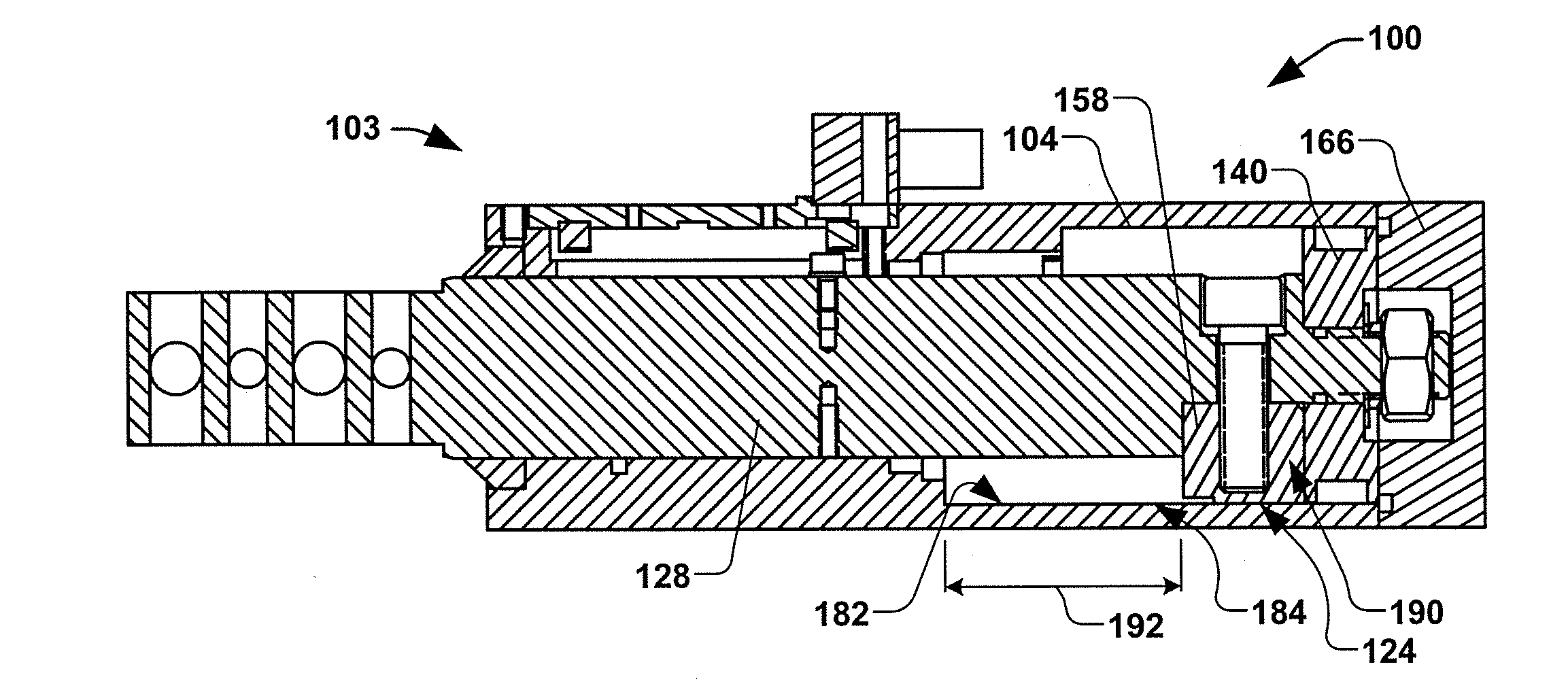
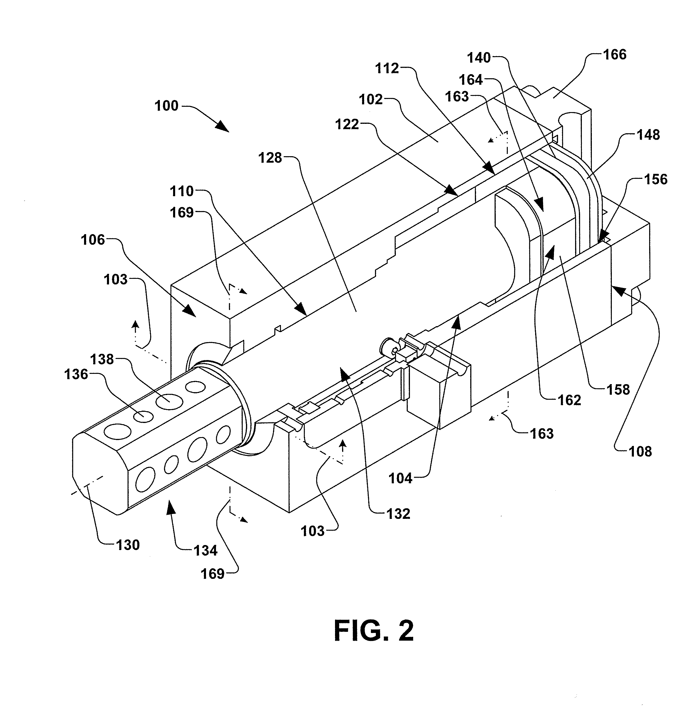
[0029]Referring now to the Figures, in accordance with the present invention, FIG. 2 illustrates a perspective partial cross-sectional view of an exemplary linear actuator 100. The linear actuator 100 comprises a housing 102 having a bore 104 extending ...


PUM


Abstract

A linear actuator is provided having a housing with a bore having at least first and second portions extending therethrough. The second portion has a polygonal geometry with substantially rounded corners having at least one planar bearing surface. A shaft is in sliding engagement with the first portion of the bore, and a piston member is operatively coupled to the shaft. The piston member has a mating geometry to the second portion of the bore, wherein the piston member is in sliding engagement with the second portion of the bore. An anti-rotation member is coupled to the piston member or shaft and has a generally D-shaped geometry with a planar anti-rotation bearing surface. Contact between the anti-rotation member and the housing is limited to a sliding engagement between the anti-rotation bearing surface and one of the at least one bearing surfaces based on an orientation of the anti-rotation member.

Description

FIELD[0001]The present invention relates generally to linear actuators, and more particularly to a robust and compact linear actuator having a configurable anti-rotation device.BACKGROUND[0002]Industrial linear actuators perform a variety of functions, such as linearly translating a locating pin, or operating a clamp for maintaining a position of a workpiece. A typical linear actuator comprises a housing having a linearly-translating shaft that is operably coupled to a drive means, such as a pneumatic piston and cylinder arrangement, or a geared electric motor. In many applications, precise positioning of the linearly-translating shaft is essential to maintaining specific tolerances in a final assembly of the workpiece.[0003]It is often desirable that the shaft of the linear actuator not rotate with respect to the housing, but rather, extend in a straight line along a single axis without rotation about the axis. Thus, it is desirable that the yaw, pitch, and roll of the shaft with r...

Claims


Application Information

Patent Timeline
IPC IPC(8): F16J1/00
CPCF15B15/1419F15B15/1414
Inventor ZAJAC, JR., THEODORE S.ISELIN, BRIAN FREDERICK
Owner ZAYTRAN
Why Eureka
Try Eureka