
Moisture responsive irrigation method and apparatus

Inactive Publication Date: 2013-10-17
CANPLAS INDS
View PDF16 Cites 8 Cited by
  • Summary
  • Abstract
  • Description
  • Claims
  • Application Information

AI Technical Summary

Benefits of technology

The present invention is a system and method for efficient and precise irrigation that saves water and prevents evaporation. It works by automatically adjusting to the needs of each plant, based on soil moisture content, and allowing the water to flow only when the plant requires it. The system is self-regulating, meaning it will adjust itself to ensure optimal irrigation. This results in more efficient water usage, better soil soaking, and reduced labor costs.

Problems solved by technology

More recently global warming has become an issue.
Water consumption is also an issue.
While efforts are being made to treat the waste water that is produced, this is not always done appropriately.
Further, in certain soil conditions, surface watering can be counterproductive.
However, generally a location that has little or no water, such as a desert or semi desert, is also characterized by high evaporation rates, meaning that surface water evaporates quickly upon being exposed.
Water that evaporates is no longer available for any plants or crops and is thus wasted from crop growing or an agricultural point of view.
A significant amount of the water used in traditional surface sprinkler irrigation is lost through evaporation, before it can ever be used by the plants being watered.
However, while efficient in reducing the amount of water used, because it is applied in small amounts directly to the individual plants and root systems, there are still problems with water loss due to evaporation.
This, providing a steady drip rate will result in over watering in some cases and under watering in other cases.
Providing a variable drip rate is very difficult.
However, these suffer from the invasion of fibrous roots seeking water which can block the tubes and disrupt the water distribution to the rest of the system.

Method used


Image

  • Moisture responsive irrigation method and apparatus
  • Moisture responsive irrigation method and apparatus
  • Moisture responsive irrigation method and apparatus

Examples


Embodiment Construction

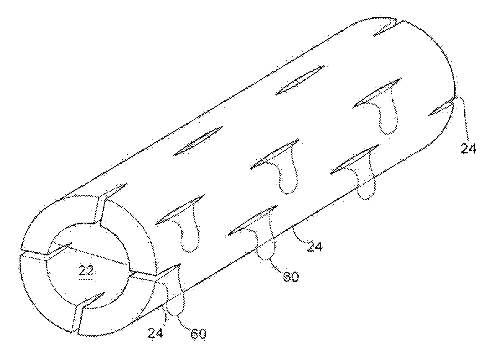
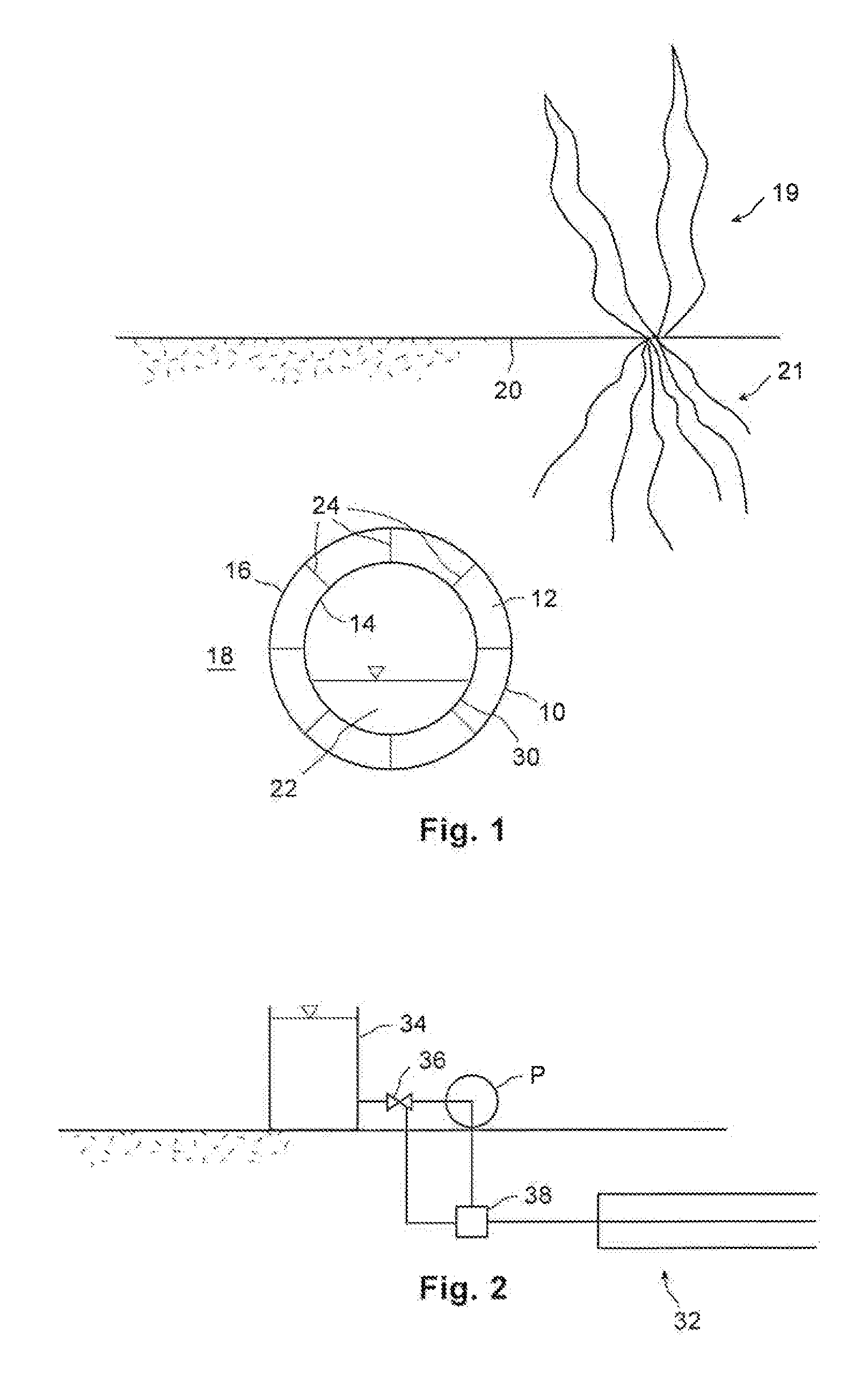
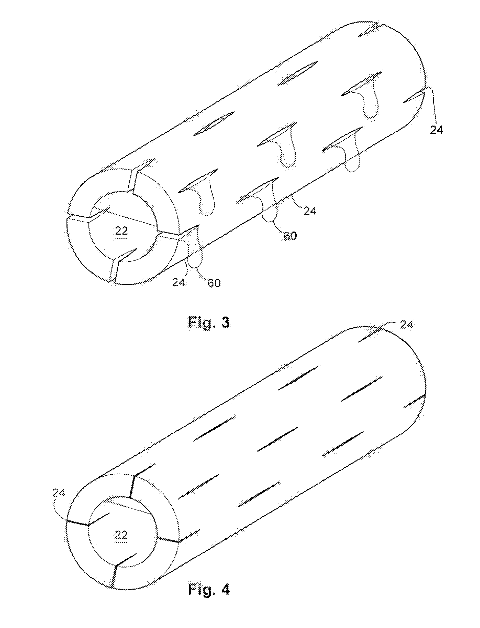
[0022]FIG. 1 shows a cross section through a watering or irrigation tube 10 according to one embodiment of the present invention. The tube 10 includes a tube wall 12 and has an inside 14 and an outside 16. As shown the tube 10 is buried and so soil 18 is located outside of the tube 10. Also shown under the ground surface 20 is a plant 19 with a root system 21. While the tube 10 may also be used in an above ground application a buried application is preferred for the reasons set out below. Water, shown as 22, is partially filling the tube 10. Perforations 24 are also shown through which the water 22 in the tube 10 can pass, thereby wetting the soil 18 and watering the root system 21 of the plant 19.

[0023]The tube 10 includes a tube wall portion 22 which has special properties to allow the tube 10 to be self-regulating in terms of how much water is passed through the perforations 24 to the plant. In particular the tube 10 is formed from a water swellable material associated with the p...


PUM


Abstract

An irrigation device comprising a moisture responsive barrier is provided. At least a portion of the barrier has perforations, at least some of the perforations are associated with a water swellable material. The perforations are configured to open as the water swellable material loses moisture and dries out and are configured to close as said water swellable material is exposed to and absorbs water, such as during a watering step. According to another aspect the irrigation method includes the steps of positioning a perforated barrier between a source of irrigation water and an area to be irrigated, wherein the perforations are associated with a water swellable material; exposing the water swellable material to water to cause the water swellable material to swell to close the perforations; and permitting the water swellable material to dry, to open the perforations, whereby the opening and closing of the perforations regulates the amount of irrigation water being applied across the barrier in the irrigation method.

Description

FIELD OF THE INVENTION[0001]This invention relates generally to plant irrigation, and more particularly relates to ground water irrigation of the type that dispenses irrigation water for example through a hose or water conduit directly to the soil around the roots of plants to avoid evaporative losses and thus to conserve water for plant growth purposes.BACKGROUND OF THE INVENTION[0002]Humans have been cultivating crops since before recorded time. The earliest and most successful growing locations combined good growing conditions, such as plenty of water and sunlight with good fertile soil conditions. However, as the human population continues to expand, ever more crops are required. Out of necessity crop science advances have been made, including using fertilizer to make the soil more fertile and advancing plant and crop genetics to increase crop yields from the same acreage. As well many different types of irrigation systems have been developed to extend the amount of plantable ar...

Claims


Application Information

Patent Timeline
IPC IPC(8): A01G25/02
CPCA01G25/02A01G25/06Y10T137/189
Inventor BAYLEY, JEFF
Owner CANPLAS INDS
Learn More