
Electrical power stab system and method for making same

a technology of electrical power distribution and stab system, which is applied in the direction of contact member manufacturing, coupling device connection, multiple conductor connector, etc., can solve the problems of insufficient connectivity, high cost and cumbersome method, and complex distribution system of electrical power for residential, commercial and industrial use, etc., and achieves the effect of higher conductivity

Inactive Publication Date: 2013-10-17
ROCKWELL AUTOMATION TECH
View PDF4 Cites 6 Cited by
  • Summary
  • Abstract
  • Description
  • Claims
  • Application Information

AI Technical Summary

Benefits of technology

The patent text describes an electrical power stab system that includes two conductors with a conductive layer and a spring biasing layer. This design allows for the conductive layer to make electrical contact with a mating stab element. Another version of the system includes a conductive material bonded to a high-elastic modulus material, which pushes the conductive material towards the contact position. Additionally, a method is described where a conductive material is bonded to a spring steel material to create an electrical stab contact, with the conductive material being at least as thick as the steel material. These technical effects improve the reliability and efficiency of electrical power stabs in high-voltage applications.

Problems solved by technology

Systems that distribute electrical power for residential, commercial, and industrial uses can be complex and widely divergent in design and operation.
One continuing issue in such systems ensuring the quality of the electric connection made between the stab and the bus bars disposed on the vertical bus.
However, this method can be costly and cumbersome, and may not offer optimal connectivity over time.
In particular, the spring forces that serve to ensure good connections may not be consistent, consistently distributed, and may decay over time due to material creep, temperature variation, and so forth.

Method used


Image

  • Electrical power stab system and method for making same
  • Electrical power stab system and method for making same
  • Electrical power stab system and method for making same

Examples


Embodiment Construction

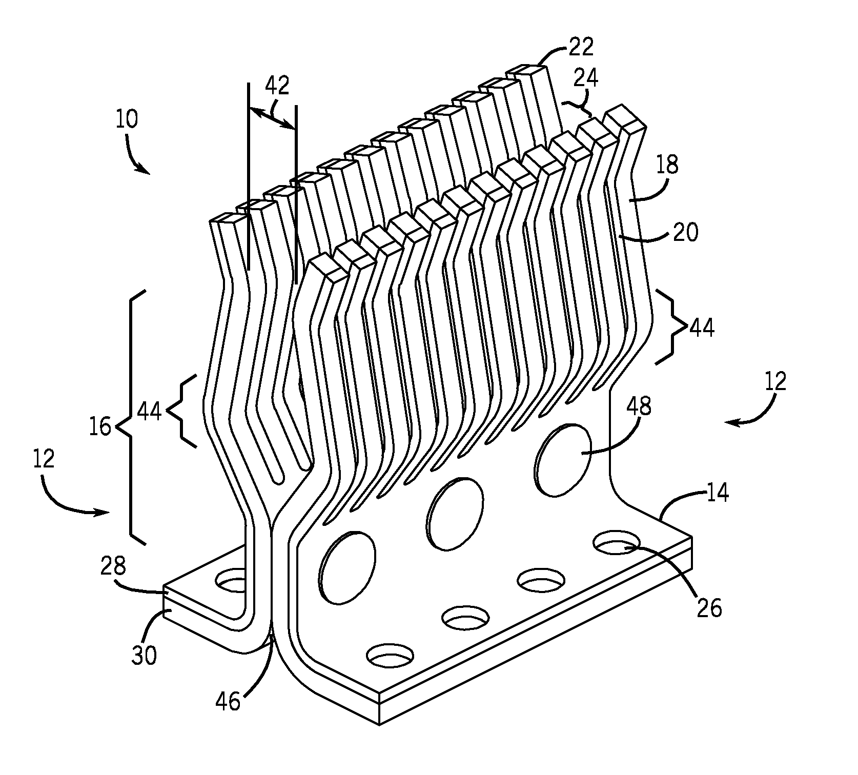
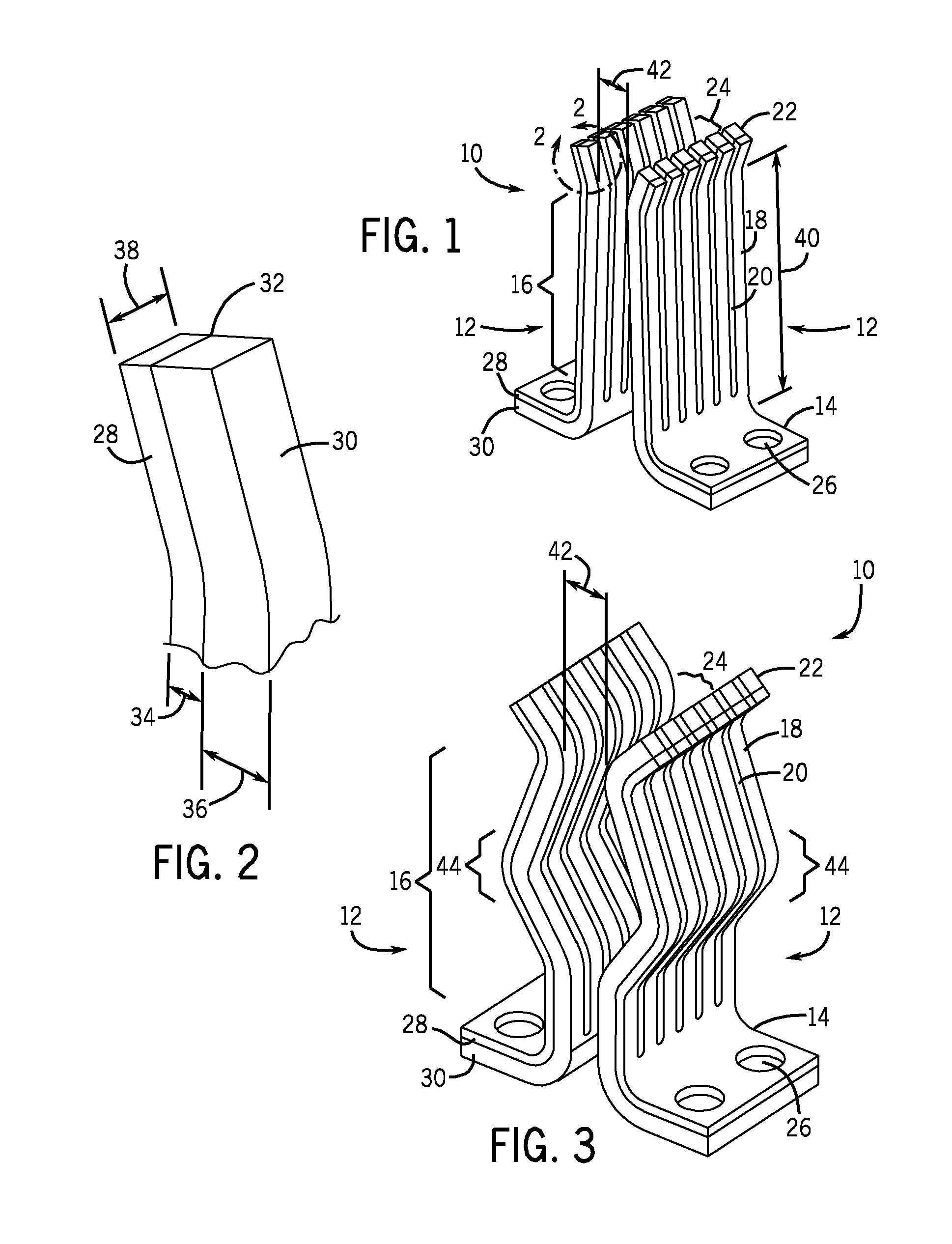
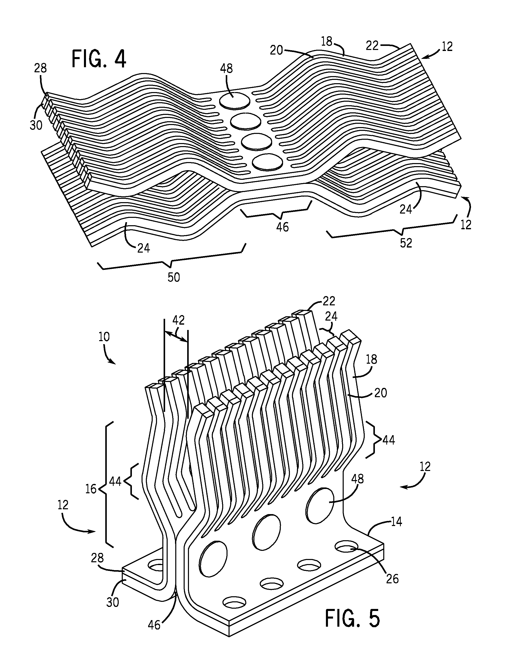
[0021]Referring generally to FIG. 1, one embodiment of a stab fork assembly 10 is illustrated. The embodied stab fork assembly 10 includes two stab forks 12 disposed in generally mutually facing relation. Each of the stab forks 12 further comprises a base 14, a body 16 comprising a plurality of fingers 18 separated by a plurality of slits 20, and outwardly bending tips 22 where the fingers 18 terminate. The body 16 is generally disposed at an angle in relation to the base 14. Specifically, the body 16 is generally vertically oriented, while the base 14 is generally horizontally oriented, or vice versa, depending on the viewing angle, as illustrated in FIG. 1. The two tips 22 generally bend outwardly toward opposing directions, forming a primary contact region 24 between the stab forks 12 at the point of inflection of the outwardly bending tips. The primary contact region 24 is generally where a stab would first make contact with the stab fork assembly 10 during making of the connect...


PUM

PropertyMeasurementUnit
conductivityaaaaaaaaaa
thickaaaaaaaaaa
thicknessaaaaaaaaaa

Abstract

A power stab fork system is provided for power stab systems. The system comprises stab forks made of a steel layer bonded to a layer of highly conductive material such that the highly conductive material effectively conducts power with stabs while the steel layer keeps the stab fork in robust contact with the stab because of its stronger material properties. The stab forks may comprise a plurality of fingers for making independent contacts points onto a stab. Some embodiments included stab forks with one forked end, two forked ends, straight fingers, curved fingers, separated stab forks, conjoined stab forks, and so forth.

Description

BACKGROUND[0001]The invention relates generally to the field of power supply and distribution, such as that to and with motor control centers. Specifically, the invention relates to techniques for connecting incoming power supply to certain types of electrical machinery.[0002]Systems that distribute electrical power for residential, commercial, and industrial uses can be complex and widely divergent in design and operation. Electrical power generated at a power plant may be processed and distributed via substations, transformers, power lines, and so forth, prior to receipt by the end user. The user may receive the power over a wide range of voltages, depending on availability, intended use, and other factors. In large commercial and industrial operations, the power may be supplied as three phase AC power (e.g., 208 to 690 volt AC, and higher) from a main power line to a power management system. Power distribution and control equipment then conditions the power and applies it to load...

Claims


Application Information

Patent Timeline
Patent Type & Authority Applications(United States)
IPC IPC(8): H01R4/48H01R43/00
CPCH01R13/113H01R43/16Y10T29/49117H01R4/4823
Inventor AHANGAR, ABDOLMEHDI KAVEHKAISHIAN, STEVEN CHARLES
Owner ROCKWELL AUTOMATION TECH
Learn More