Drive device for a motor vehicle

Inactive Publication Date: 2013-10-17
SIEMENS AG
View PDF13 Cites 9 Cited by
  • Summary
  • Abstract
  • Description
  • Claims
  • Application Information

AI Technical Summary

Benefits of technology

[0029]Advantageously, all wheel sets of the transmission device may be connected to one another in the direction of a flow of force and/or tor

Problems solved by technology

Reversibly-releasable connections, which for example may involve flanged connections

Method used


Image

  • Drive device for a motor vehicle
  • Drive device for a motor vehicle

Examples


Example

[0031]The depicted embodiment is to be understood as illustrative of the invention and not as limiting in any way. It should also be understood that the figure is not necessarily to scale and that the embodiment may be illustrated by graphic symbols, phantom lines, diagrammatic representations and fragmentary views. In certain instances, details which are not necessary for an understanding of the present invention or which render other details difficult to perceive may have been omitted. The features and combinations of features specified in the description as well as the features and combinations of features specified in the description of the FIGURE and / or in the FIGURE alone are able to be used not only in the respectively specified combination, but also in other combinations or on their own, without departing from the framework of the invention.

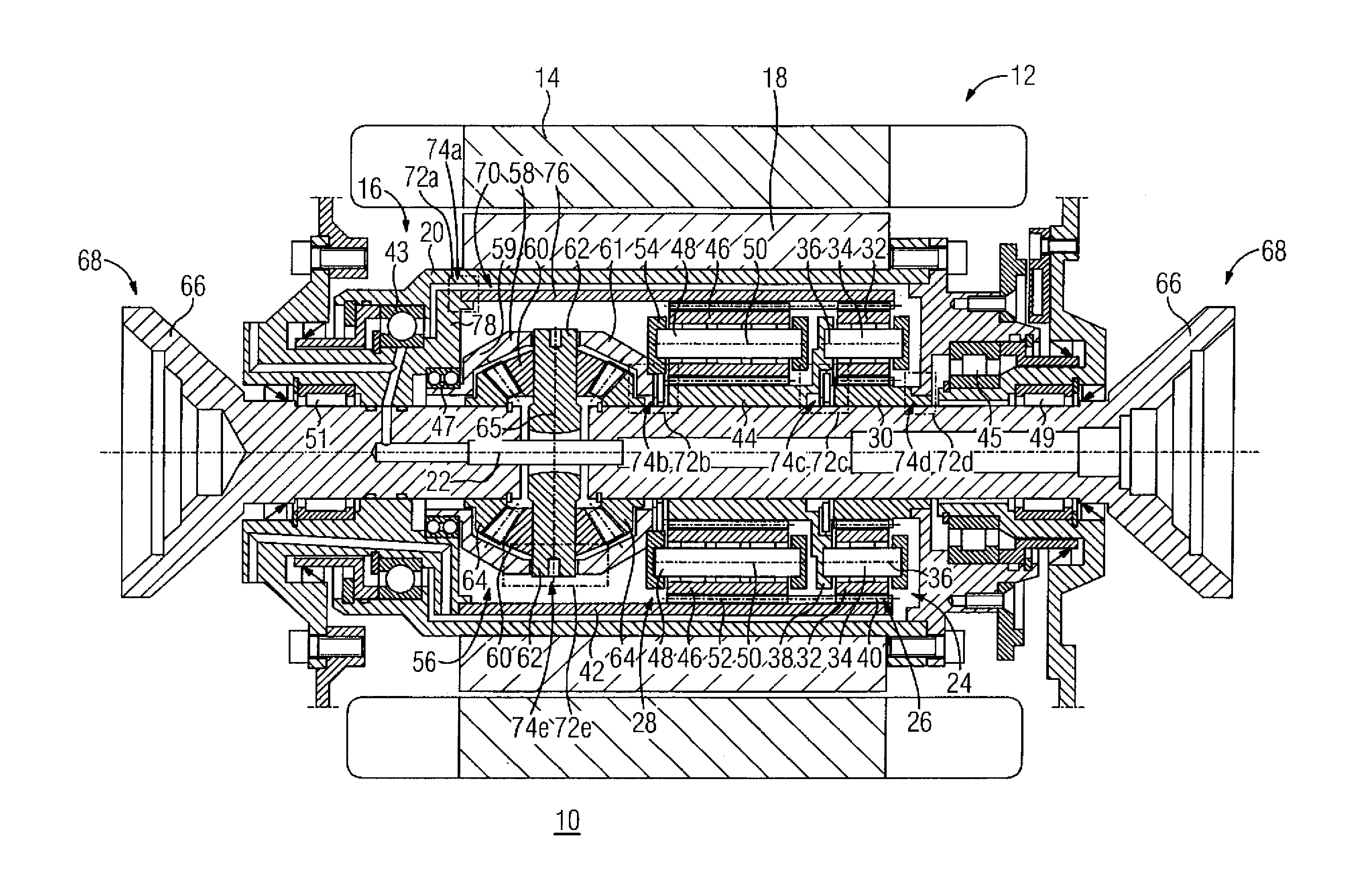
[0032]Turning now to the FIGURE, there is shown a schematic longitudinal sectional view of a drive device for a motor vehicle embodied f...


PUM


Abstract

A drive device for a motor vehicle includes at least one electric machine having at least one rotor element which is configured to delimit an installation area in a radial direction. At least one transmission device is disposed, at least partly, in the installation area and configured to be driven by the electric machine via the rotor element. At least two components of the transmission device and/or electric machine are permanently linked to one another such that a detachment of the two components causes destruction.

Description

CROSS-REFERENCES TO RELATED APPLICATIONS[0001]This application claims the priority of German Patent Application, Ser. No. DE 10 2012 206 143.6, filed Apr. 16, 2012, pursuant to 35 U.S.C. 119(a)-(d), the content of which is incorporated herein by reference in its entirety as if fully set forth herein.BACKGROUND OF THE INVENTION[0002]The present invention relates to a drive device for a motor vehicle.[0003]The following discussion of related art is provided to assist the reader in understanding the advantages of the invention, and is not to be construed as an admission that this related art is prior art to this invention.[0004]Drive devices for motor vehicles have been described in the prior art and are also known from series production of motor vehicles, especially of automobiles. Typically, a drive device includes a drive unit and if necessary a transmission, via which the motor vehicle is able to be driven. The drive unit involves an internal combustion engine for example. As an al...

Claims


Application Information

Patent Timeline
IPC IPC(8): F16H57/037F16H57/031
CPCF16H57/037F16H57/031B60K1/00B60K2001/001B60L15/20B60L2220/46B60L2240/423B60L2240/461F16H2057/02034Y02T10/64Y02T10/72Y10T74/19684Y10T74/2186
Inventor KALMBACH, KLAUSSCHLEICHER, KLAUSSTEINZ, JANINA
Owner SIEMENS AG
Why Eureka
Try Eureka