Power tool

Inactive Publication Date: 2013-10-24
HITACHI KOKI CO LTD
View PDF6 Cites 12 Cited by
  • Summary
  • Abstract
  • Description
  • Claims
  • Application Information

AI Technical Summary

Benefits of technology

[0018]According to the present invention, a part of the grip is made of an elastic body formed by compression molding, thereby allowing the elastic body to have uneven thickness. Accordingly, the thickness of the elast

Problems solved by technology

Thus, vibration of the motor and a speed reduction mechanism, reaction from the tip tool, etc. produced during wor

Method used


Image

  • Power tool
  • Power tool
  • Power tool

Examples


Embodiment Construction

[0042]Hereinafter, with reference to the drawings, an embodiment of the present invention will be described in detail.

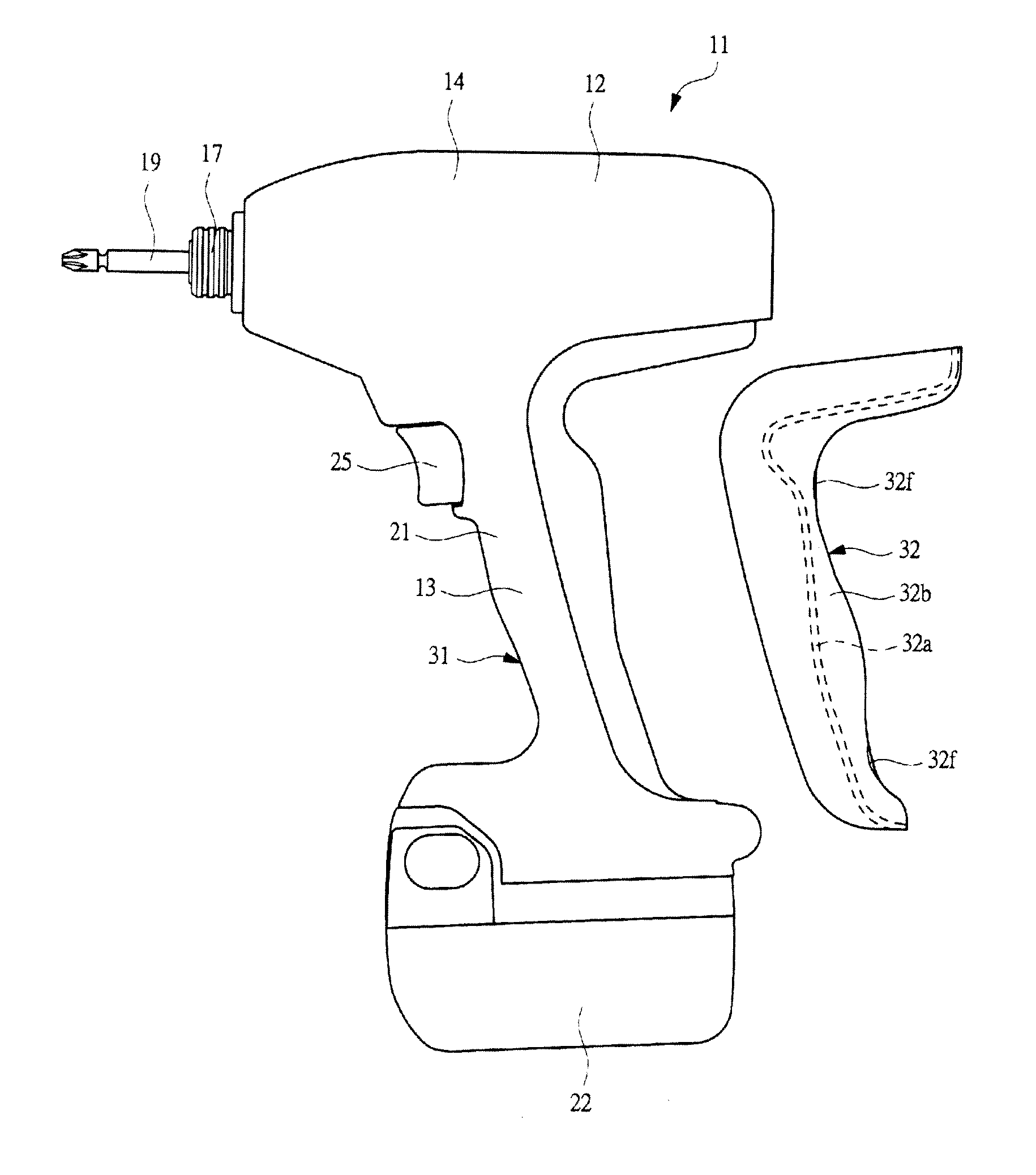
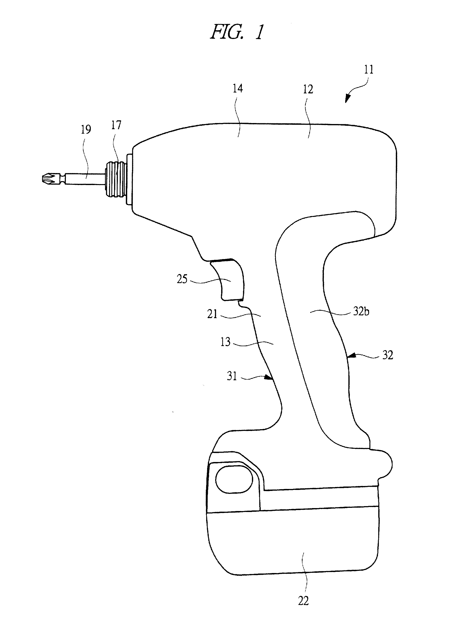
[0043]An impact driver 11 as a power tool shown in FIG. 1 is a hand-held electric power tool which is used for fastening or loosening fastening members such as screws and bolts.

[0044]The impact driver 11 includes: a body portion 12 formed in a shell-like shape; and a grip section 13 extending from about a central part in an axial direction of the body portion 12 toward a direction substantially perpendicular to the axial direction.

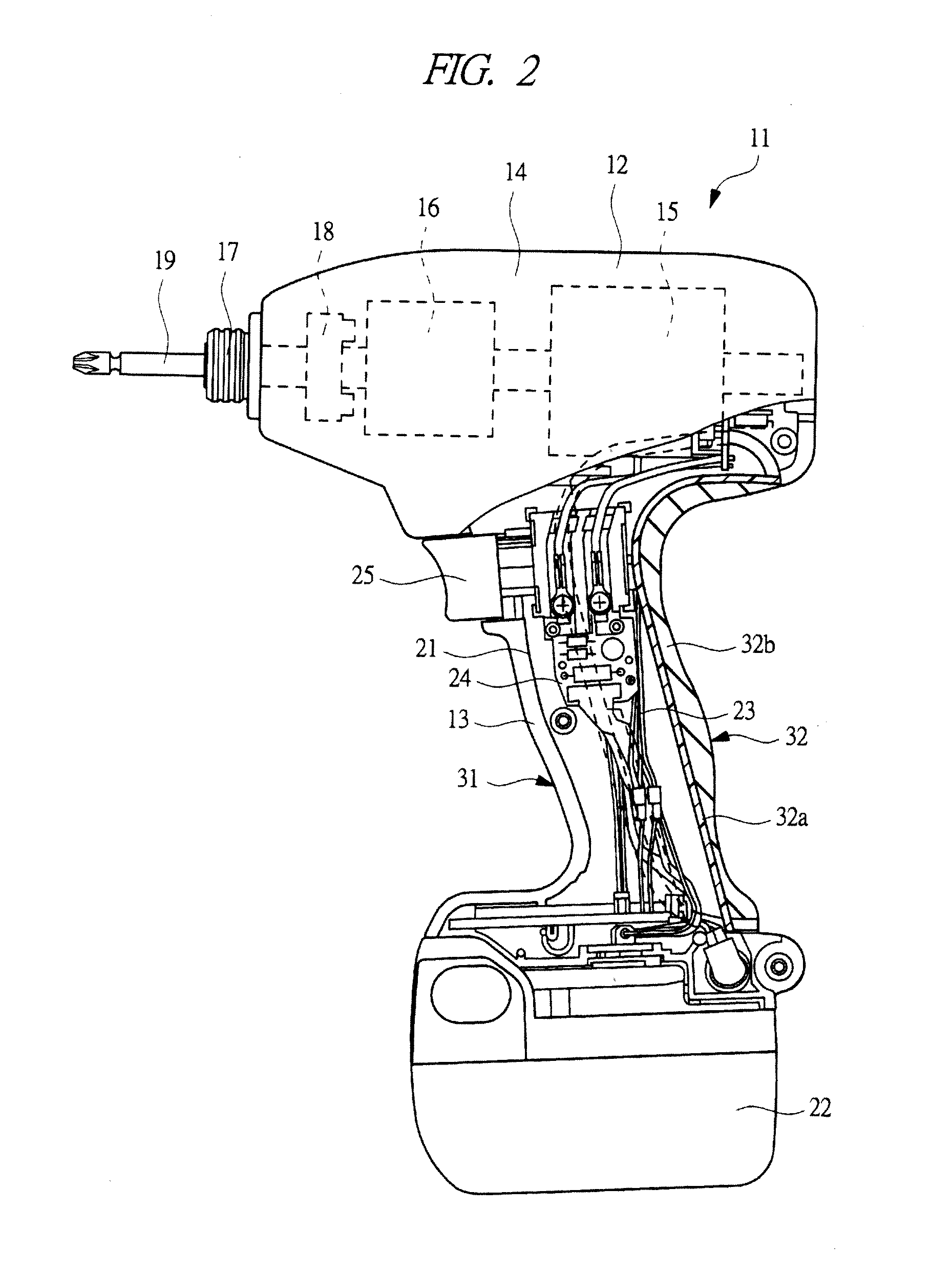
[0045]The outer covering of the body portion 12 includes a motor housing 14 made of a resin. The motor housing 14 houses: an electric motor 15 serving as a motor (driving source); and a speed reduction mechanism 16. A tool holder 17 such as a socket and a chuck is rotatably supported on a tip of the motor housing 14. The tool holder 17 is connected to the electric motor 15 through the speed reduction mechanism 16.

[0046]Between the speed red...


PUM


Abstract

A hand-held power tool capable of reducing strain on a worker's fingers which might be caused by vibration and reaction during work is provided. A grip section, which is extending from substantially a central part in an axial direction of the body portion toward a direction substantially perpendicular to the axial direction, is integrally provided on a body portion having a motor housing. A grip housing configuring the grip section is provided so as to extend from the motor housing. The grip housing includes a housing body including a pair of housing pieces and a cover sandwiched to be held by the housing pieces. The cover includes a compression-molded article in which a resin cover body and a rubber member are integrally formed by compression molding.

Description

TECHNICAL FIELD[0001]The present invention relates to a hand-held power tool in which a grip housing is provided so as to extend from a motor housing which houses a motor.BACKGROUND ART[0002]A hand-held power tool such as an impact driver and a hammer drill includes: a tool holder to which tip tools such as a bit and a drill are attached; and a motor (driving source) which rotates the tool holder. The tool holder is rotatably supported on a tip of a motor housing, and the motor is housed in the motor housing. A grip section (handle) is integrally provided in a body portion configured in the above-described manner. The grip section is a portion which is gripped by a worker during work, and has a grip housing provided so as to extend from the motor housing. Moreover, a trigger for starting the motor is provided to a portion facing the tool holder at a root portion of the grip section. The work with use of this power tool is conducted by pulling the trigger in a state where the tip too...

Claims


Application Information

Patent Timeline
IPC IPC(8): B25F5/00
CPCB25F5/006B25F5/02
Inventor TSUZUKI, HITOSHISAKAI, MASATO
Owner HITACHI KOKI CO LTD
Why Eureka
Try Eureka