Wide-band acoustically coupled thin-film baw filter

Active Publication Date: 2013-10-24
TEKNOLOGIAN TUTKIMUSKESKUS VTT OY
View PDF6 Cites 23 Cited by
  • Summary
  • Abstract
  • Description
  • Claims
  • Application Information

AI Technical Summary

Benefits of technology

[0033]Furthermore, a LBAW filter can implement a balun functionality inside a filter, without a separate component. A balun filter with a steep pass band and a simple manufacturing process is herein possible. Resonators also act as matching elements for an LBAW filter. Compared to pure

Problems solved by technology

This limits somewhat the design of the acoustic mirror.
The disadvantage of the vertically coupled CRFs is the need for a large number of layers and their sensitivity to the thickness of the piezolayers.
This makes the fabrication process difficult and consequently expensive.
Vertical CRF's have disadvantages as they are difficult and

Method used


Image

  • Wide-band acoustically coupled thin-film baw filter
  • Wide-band acoustically coupled thin-film baw filter
  • Wide-band acoustically coupled thin-film baw filter

Examples


example filter

with Measurement Results

[0077]One exemplary example is described herein along with the corresponding measurement results from the example filter. The structure of the filter will now be described below.

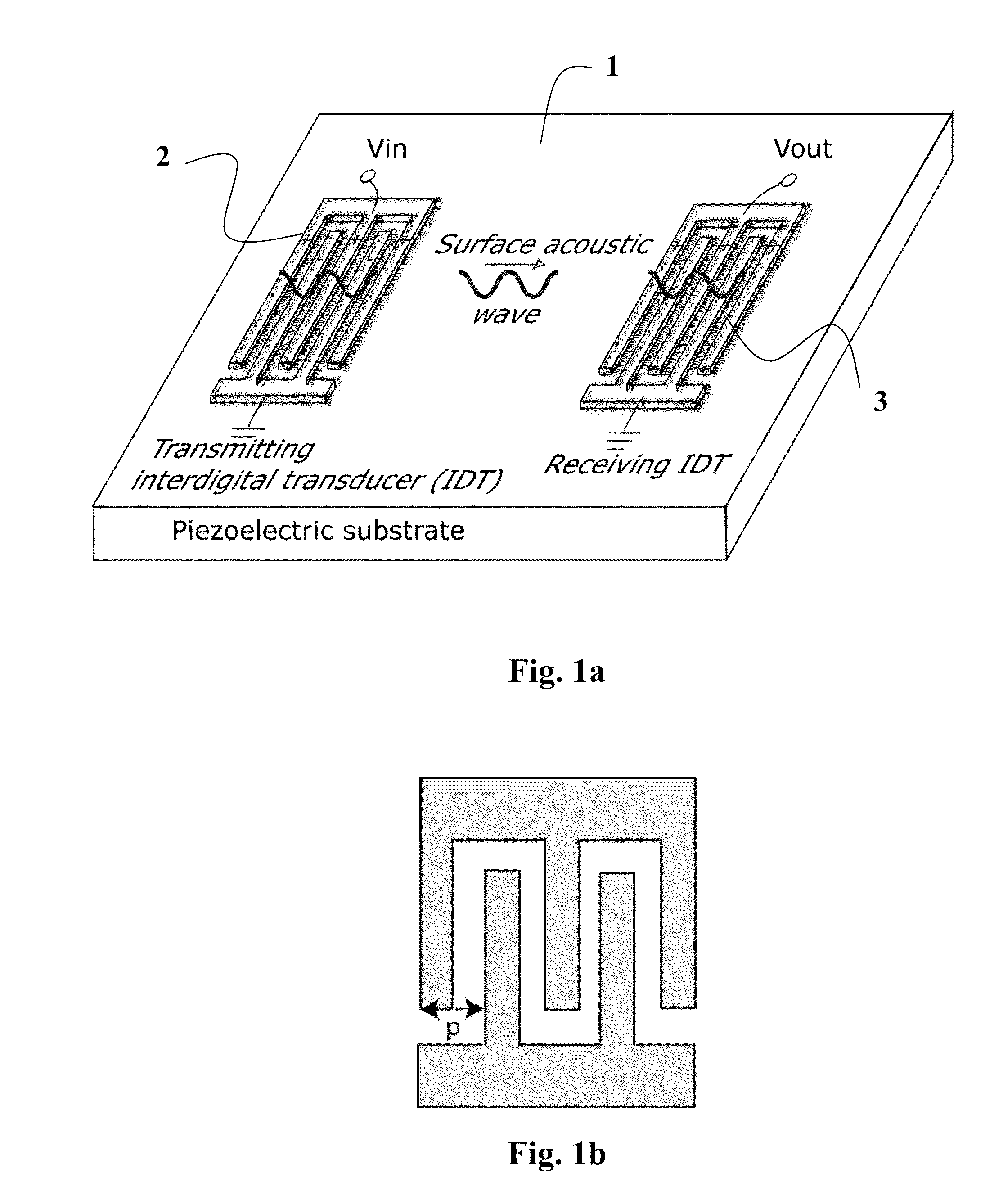
[0078]The filter of the present example consists of a thin-film stack. The nominal thin-film layer thicknesses of the acoustic stack are set forth in Table 7, from bottom to top. The substrate of the filter in the example is silicon. The electrode structure used is interdigital and similar to that shown in FIG. 1(b). A microscope image of the present example is also presented in FIG. 9. The total number of electrodes in 5 and 6 is N=31, the electrode width W=3 μm, the gap width G=2 μm, the electrode length L=200 μm and the probe pad size is 150 μm×150 μm.

[0079]Although the electrode and gap width W and G are constant in FIG. 1(b) as well as in the component introduced below in FIG. 9, the structure need not be limited to constant W / G and / or constant period.

TABLE 7Nominal layer thickne...


PUM


Abstract

The invention relates to an acoustically coupled thin-film BAW filter, comprising a piezoelectric layer, an input-port on the piezoelectric layer changing electrical signal into an acoustic wave (SAW, BAW), and an output-port on the piezoelectric layer changing acoustic signal into electrical signal. In accordance with the invention the ports include electrodes positioned close to each other, and the filter is designed to operate in first order thickness-extensional TE1 mode.

Description

FIELD OF INVENTION[0001]The present invention relates to a wide-band acoustically coupled thin-film Bulk Acoustic Wave (BAW) filter according to the preamble of Claim 1.BACKGROUND OF THE INVENTION[0002]Radio-frequency (RF) components, such as resonators and filters, based on microacoustics and thin-film technology are widely used in radio applications such as: mobile phones, wireless networks, satellite positioning, etc. Their advantages over their lumped-element counterparts include small size and mass-production capability. Two fundamental microacoustic technologies used for RF devices are surface acoustic wave (SAW) and bulk acoustic wave (BAW) technologies.[0003]In this section, existing filter technologies are briefly introduced to provide background for the current invention.Surface Acoustic Wave Devices[0004]A schematic picture of a SAW device is shown in FIG. 1(a). Interdigital transducers (IDTs) 2, 3 (comb-like structures of thin-film metal strips) are patterned on a piezoe...

Claims


Application Information

Patent Timeline
IPC IPC(8): H03H9/54
CPCH03H9/547H03H9/564H03H9/568H03H3/02
Inventor MELTAUS, JOHANNAPENSALA, TUOMAS
Owner TEKNOLOGIAN TUTKIMUSKESKUS VTT OY
Why Eureka
Try Eureka