Illumination assembly and display module

a technology of illumination assembly and display module, which is applied in the direction of lighting and heating equipment, planar/plate-like light guides, instruments, etc., can solve the problems of increasing the thickness of the entire display module, increasing the border width, and not being readable by users, so as to reduce the overall thickness and the border width of the display module, and the height of the illumination assembly raised on the display panel can be greatly reduced.

Active Publication Date: 2013-10-24
WISTRON CORP
View PDF2 Cites 8 Cited by
  • Summary
  • Abstract
  • Description
  • Claims
  • Application Information

AI Technical Summary

Benefits of technology

[0013]By transferring the travelling direction of the visual light through the light guide, the visual-light source is able to be disposed on the substrate and hidden between the substrate and the display panel. Therefore, in the embodiments of the disclosure, the visual-light source does ...

Problems solved by technology

However, under a low illumination environment, the screen displayed on such reflective type display panel is not readable for by user.
However, the design of two stacked light guides and a reflecting component in U.S. Pat. No. 6,951,401 obviously increase the thickness of the entire display module.
In U.S. Pat. No. 6,341,872, the display module must reserve a certain borde...

Method used


Image

  • Illumination assembly and display module
  • Illumination assembly and display module
  • Illumination assembly and display module

Examples


Embodiment Construction

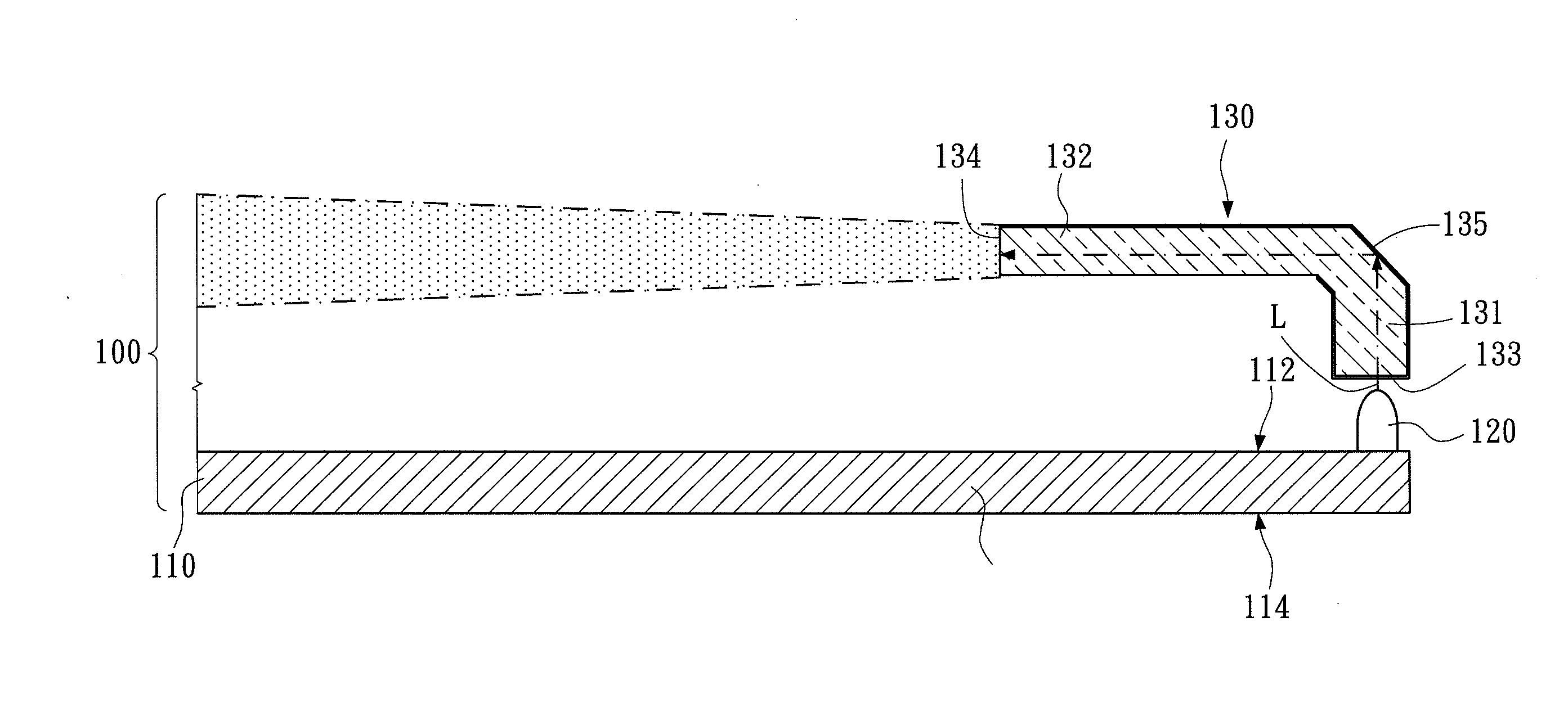
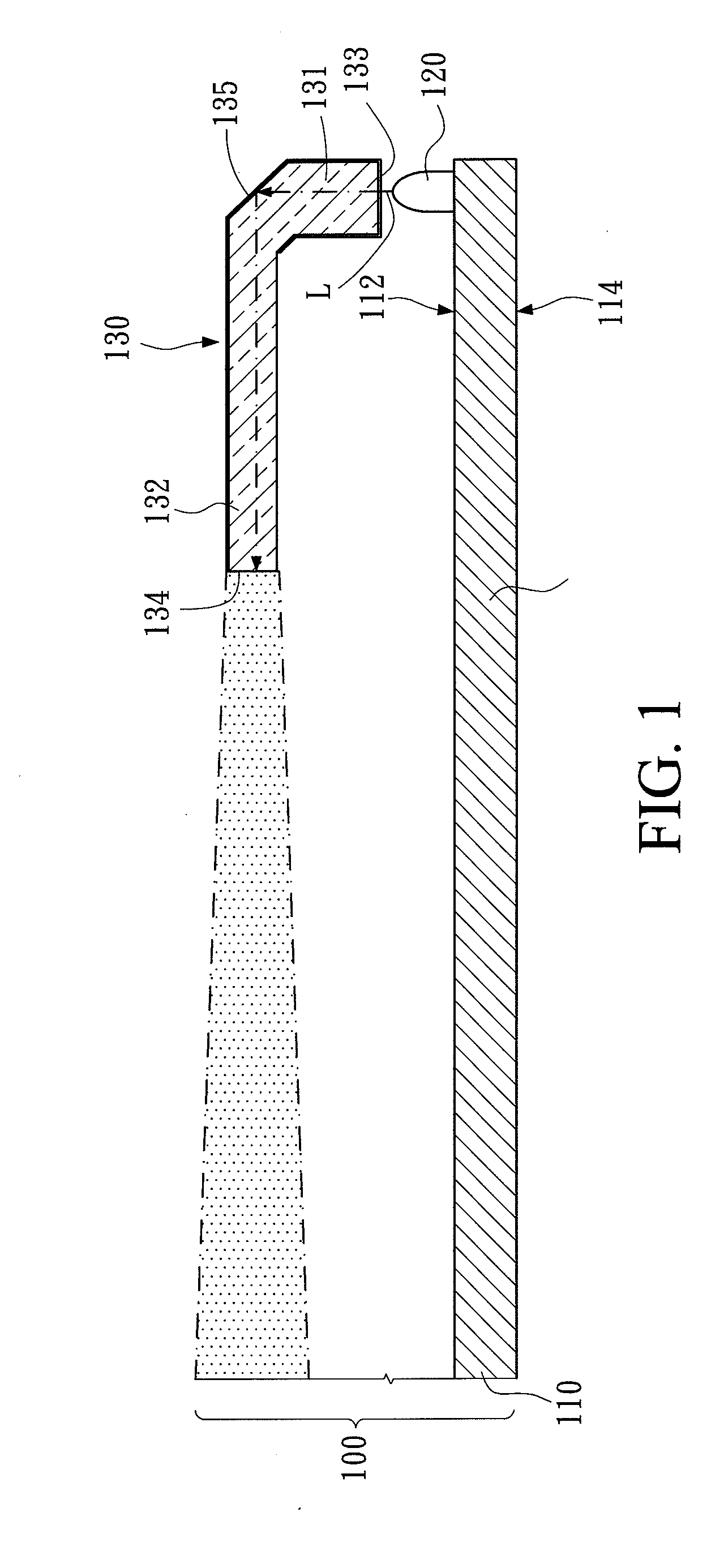
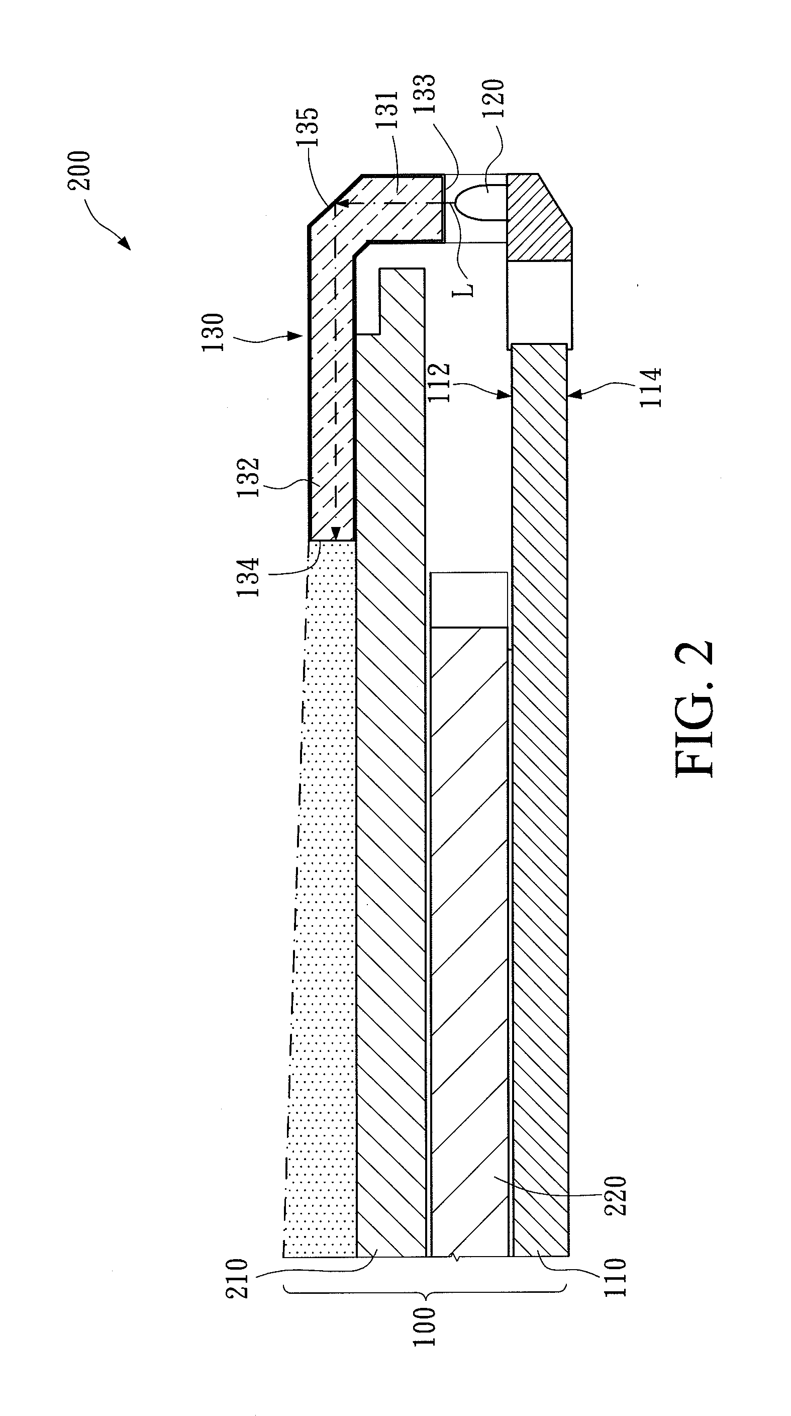
[0023]Please refer to FIG. 1, which illustrates an illumination assembly 100 according to a first embodiment of the disclosure. The illumination assembly 100 is adapted to illuminate a display panel 210 that is visible by reflecting environmental lights. The illumination assembly 100 includes a substrate 110, a visual-light source 120 and a light guide 130.

[0024]As shown in FIG. 1, the substrate 110 may be realized by a printed circuit board or a general board with distributed electrical wires for providing electric power and signal transmissions. The substrate 110 is disposed in an accommodating space within an electronic apparatus and is fixed inside the housing of the electronic apparatus. The substrate 110 includes a top surface 112 and a bottom surface 114. The top surface 112 and the bottom surface 114 are designed for disposing different components, and are both electrically connected with electric circuits of the substrate 110.

[0025]As shown in FIG. 1, the visual-light sourc...


PUM


Abstract

An illumination assembly is adapted to illuminate a display module that is visible by reflecting environmental lights. The illumination assembly includes a substrate, a visual-light source, and a light guide. The substrate includes a top surface. The visual-light source is disposed on the top surface and is provided for emitting a visual light. The light guide is disposed corresponding to the top surface of the substrate. The light guide includes a light-incidence surface and a light-emergence surface. The visual light enters the light guide through the light-incidence surface and is reflected at least once. The visual light then exits the light guide through the light-emergence surface and travels along a light-emergence direction.

Description

CROSS-REFERENCES TO RELATED APPLICATIONS[0001]This non-provisional application claims priority under 35 U.S.C. §119(a) on Patent Application No. 101114239 filed in Taiwan, R.O.C. on Apr. 4, 2012, the entire contents of which are hereby incorporated by reference.BACKGROUND[0002]1. Technical Field[0003]The disclosure relates to an illumination assembly, in particular to an illumination assembly adapted to illuminate a display panel that is visible by reflecting environmental lights.[0004]2. Related Art[0005]Electro-Phoretic Display (EPD, also known as E-paper) has characteristics such as low power consumption and suitability for long term reading, and is therefore applied broadly to E-book apparatuses as the display panel installed therein.[0006]EPD basically applies reflective-display technology, which displays a visible screen for a user mainly by reflecting environmental lights. However, under a low illumination environment, the screen displayed on such reflective type display pane...

Claims


Application Information

Patent Timeline
IPC IPC(8): F21V7/04F21V8/00
CPCG02B6/4298G02B6/0018
Inventor HUANG, SHENG-SHAN
Owner WISTRON CORP
Why Eureka
Try Eureka