

Energy efficient high-temperature refining
a high-temperature refining and high-temperature technology, applied in the field of energy-efficient high-temperature refining, can solve the problems of high energy cost, collapse of the entire system, and increased complexity and costs, and achieve the effect of reducing undesired heat discharg
- Summary
- Abstract
- Description
- Claims
- Application Information
AI Technical Summary
Benefits of technology
Problems solved by technology
Method used
Image

Examples
second embodiment
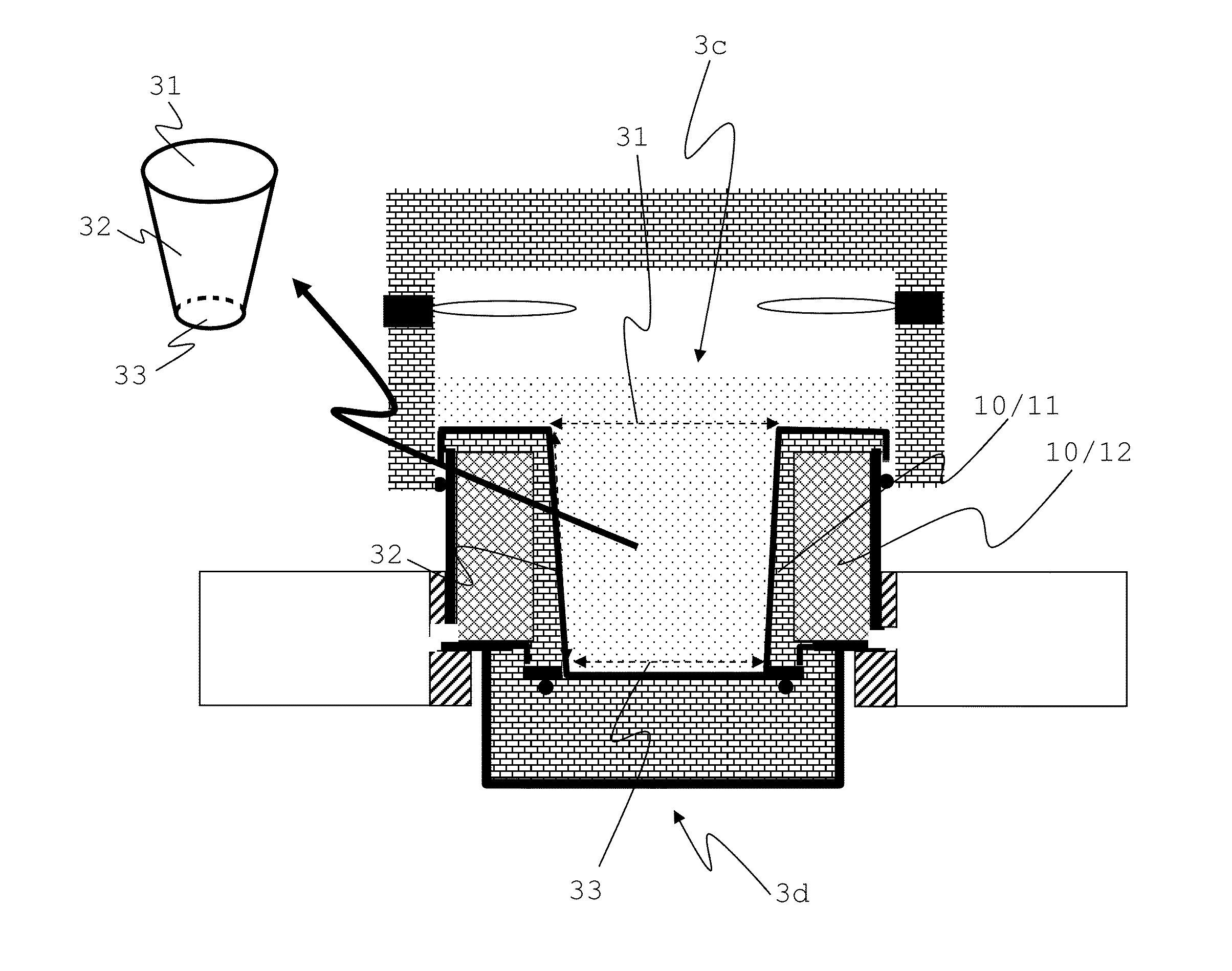
[0090]FIG. 2.b shows a refining crucible 3 designed according to the invention. It has an inlet 3a for the melt 1, which is arranged in the upper region of refining crucible 3. Outlet 3b is also arranged in the upper region of refining crucible 3, but on an opposite side relative to inlet 3a. Refining crucible 3 is a kind of a vessel which is open at its upper end face or top surface 31 or upper side and closed at its lower side or base surface 33 by a bottom. Refining crucible 3 may have a shape of a straight or oblique truncated cone in sections thereof. At the inner surface of refining crucible 3, a lining 50 is disposed as a melt contact surface, which is heated conductively and optionally, in addition thereto, inductively. Melt 1 laterally enters into refining crucible 3 from above. Melt 1 enters refining crucible 3 at a temperature from about 1500° C. to about 1600° C. First, the melt 1 falls downwards within refining crucible 3. It flows along heated lining 50. By heated lini...
third embodiment
[0109]FIGS. 4.a to 4.d schematically illustrate a refining crucible 3 having a three-layered wall 10. First, FIG. 4.a shows a horizontal cross-section of refining crucible 3 without the electrical coupling means 66 and 68 to the pair of heating means 71 and 72, which are not shown here.
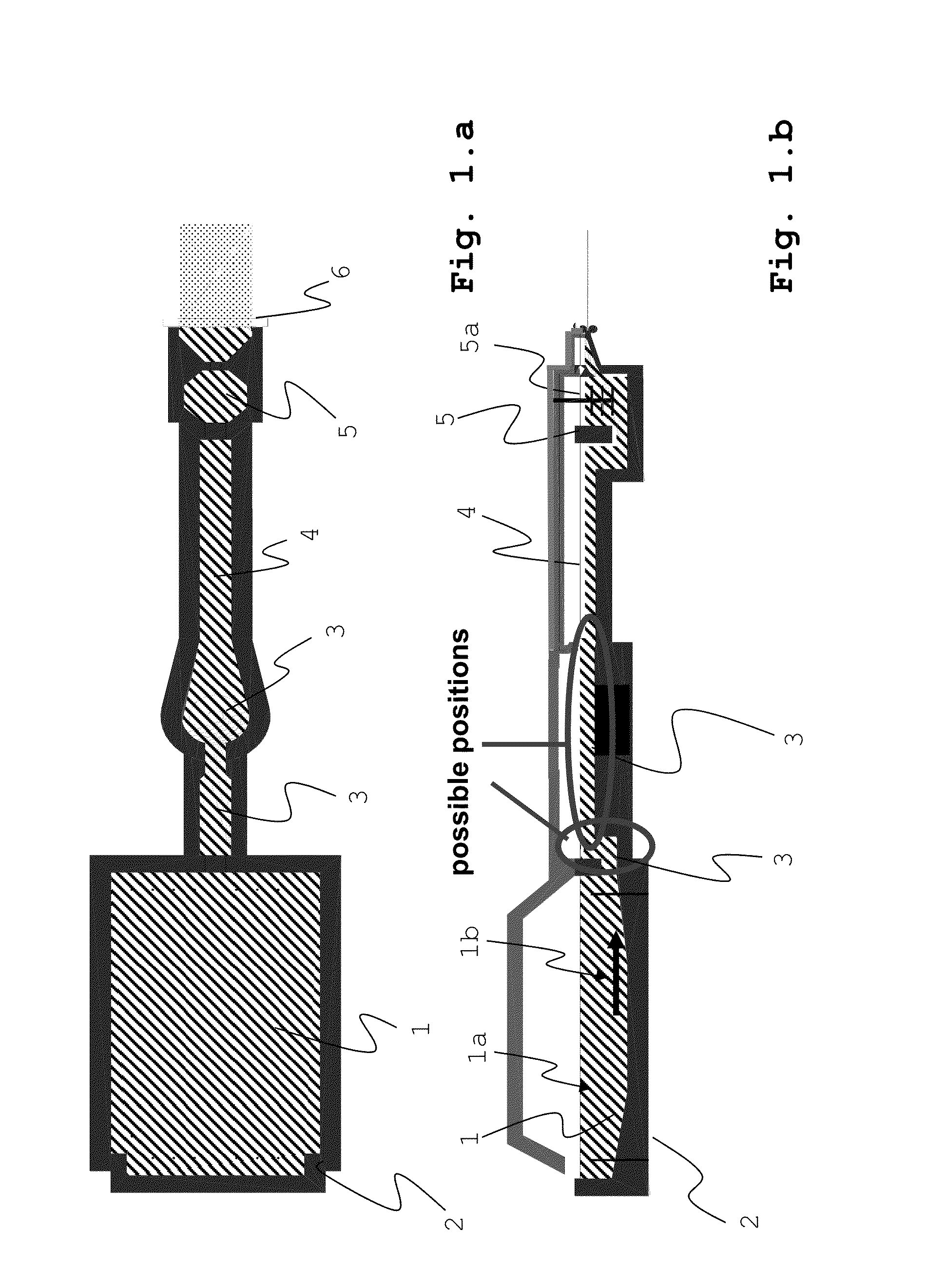
[0110]Refining crucible 3 has a so-called “top-feed”, i.e. an inlet 3a from above. The flow direction 1b of the melt 1 is indicated by arrows. The melt 1 flows laterally, in the present case from the left, along the upper surface of lateral wall 10 into crucible 3 and flows downwards after having passed the edge. By being successively heated inside crucible 3 through the heated wall 10 or lining 50, the melt 1 rises upwards again, rising above the upper edge of lateral wall 10, and then flows laterally outwards, to the right side in the present example. The melt 1 flows in parallel to or along the connecting line of the two heating means 71 and 72. In one variation of the invention, the melt may also ...
first embodiment
[0154]FIG. 8.a shows glazing collar 80 according to the invention. The collar 51 of lining 50 extends beyond the outer edge of lateral wall 10, “bends” downward and engages connecting member 67 or the flange for heating the lining 50. In this manner, a electrical connection is established. Preferably, lining 50 or the end of lining 51 resiliently engages connecting member 67, so that thermal linear expansion can be compensated for. To this end, preferably, the end edge of lining 50 is “bent”. Between the lining 50, the head end of connecting member 67 and a refractory material 42 which is covered by a Pt sheet 44, for example, an intermediate space is formed which can be filled with the melt 1. Connecting member 67 has an L-shape. Below the upper horizontal leg thereof, a cooling means 81 is arranged, for example a water-carrying pipe. This permits the melt 1 that flows into the intermediate space to freeze to form a protective jacket of intrinsic material and to close the transitio...
PUM
| Property | Measurement | Unit |
|---|---|---|
| Frequency | aaaaa | aaaaa |
| Frequency | aaaaa | aaaaa |
| Temperature | aaaaa | aaaaa |
Abstract
Description
Claims
Application Information