Transporting apparatus

a technology of transporting apparatus and cylinder, which is applied in the direction of transportation and packaging, pile separation, instruments, etc., can solve the problems of not being able to stop the material to be transported (sheet) at a target position with high accuracy, and not being able to recover, so as to achieve high accuracy and suppress the effect of

Active Publication Date: 2013-10-24
BROTHER KOGYO KK
View PDF2 Cites 7 Cited by
  • Summary
  • Abstract
  • Description
  • Claims
  • Application Information

AI Technical Summary

Benefits of technology

[0012]According to the present invention, it is possible to suppress an effect due to an increase in a load than in a conventio

Problems solved by technology

Therefore, it is not possible to recover an error in a transporting amount which is caused while switching over a velocity table to be used from the first

Method used


Image

  • Transporting apparatus
  • Transporting apparatus
  • Transporting apparatus

Examples


first embodiment

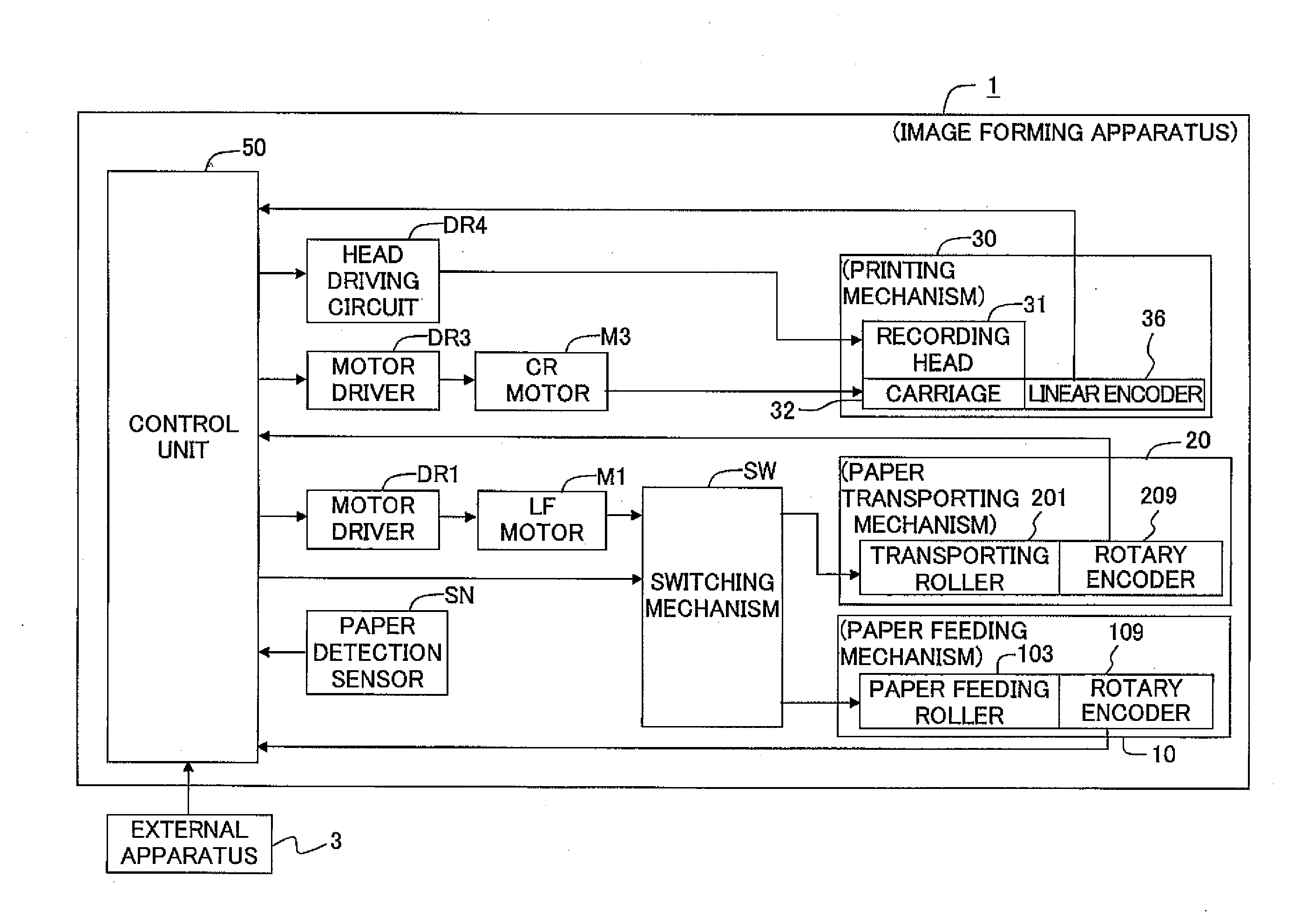
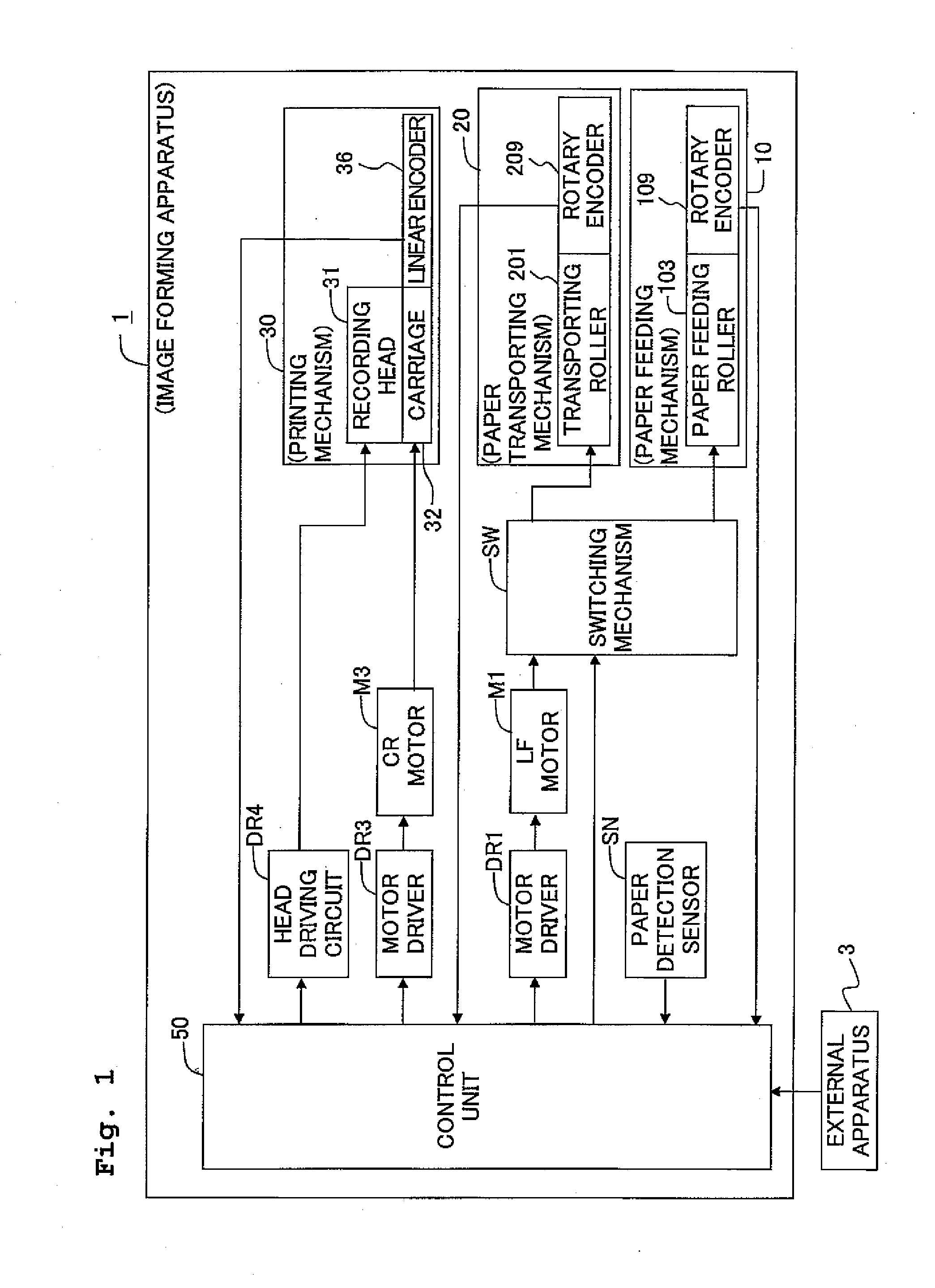
[0039]An image forming apparatus 1 according to a first embodiment is a so-called ink-jet printer. As shown in FIG. 1, the image forming apparatus 1 includes a paper feeding mechanism 10, a paper transporting mechanism 20, a printing mechanism 30, a control unit 50, a switching mechanism SW, an LF motor M1, a motor driver DR1, a CR motor M3, a motor driver DR3, a head driving circuit DR4, and a paper detection sensor SN.

[0040]The LF motor M1 is a direct current motor which applies a motive force to the paper feeding mechanism 10 and the paper transporting mechanism 20 via the switching mechanism SW, and is driven by the motor driver DR1. The switching mechanism SW is controlled by the control unit 50, and connects the LF motor M1 to one of the paper feeding mechanism 10 and the paper transporting mechanism 20.

[0041]The CR motor M3 is a direct current motor which applies a motive force to the printing mechanism 30, and is driven by the motor driver DR3. The head driving circuit DR4 d...

second embodiment

[0155]Next, an image forming apparatus 1 according to a second embodiment of the present invention will be described below. However, the image forming apparatus 1 according to the second embodiment is almost same as the image forming apparatus 1 according to the first embodiment except for a point that, the paper detection sensor SN is installed at an upstream side in the paper transporting direction of the paper detection sensor SN in the first embodiment, a point that a paper-feed control section 53 has a configuration as shown in FIG. 23, and outputs the velocity command value Vr following a trajectory shown in FIG. 24, and a point that a command generating section 536 executes a paper-feed control processing shown in FIGS. 25A and 25B. Therefore, an arrangement in the image forming apparatus 1 which differs from the first embodiment will be mentioned below selectively as the description of the second embodiment.

[0156]The paper-feed control section 53 according to the second embo...


PUM


Abstract

A transporting apparatus includes a motor, a transporting mechanism which receives a power from the motor and transports the sheet, and a control section which controls the motor in accordance with a predetermined control sequence to make the transporting mechanism transport the sheet up to a target position, and detects an occurrence of an electric-current saturation phenomenon in the motor. When the control section detects the occurrence of the electric-current saturation phenomenon, the control section performs correction of the predetermined control sequence including correction in which a target transporting velocity of the sheet is lowered from a predetermined value determined in the predetermined control sequence, and controls the motor in accordance with the corrected control sequence to make the transporting mechanism transport the sheet so that the sheet is stopped at the target position.

Description

CROSS REFERENCE TO RELATED APPLICATION[0001]The present invention claims priority from Japanese Patent Application No. 2012-099093, filed on Apr. 24, 2012, the disclosure of which is incorporated herein by reference in its entirety.BACKGROUND OF THE INVENTION[0002]1. Field of the Invention[0003]The present invention relates to a transporting apparatus which transports a sheet.[0004]2. Description of the Related Art[0005]An image forming apparatus such as an ink-jet printer and a reading apparatus have hitherto been known as apparatuses which transport a sheet. The ink-jet printer forms an image on a paper by jetting an ink on to a recording paper from a recording head while transporting the paper in a secondary scanning direction. The reading apparatus generates image data corresponding to an image of a document which is read by a reading head by reading an area of the document facing the reading head while transporting the document. Moreover, an apparatus which transports a paper b...

Claims


Application Information

Patent Timeline
IPC IPC(8): B65G43/00
CPCB65G43/00B41J11/42B65H3/0684B65H3/68B65H5/062B65H7/02B65H2402/46B65H2405/3322B65H2513/20B65H2553/51B65H2513/10B65H2515/70B65H2220/03B65H2220/11B65H2220/02B65H2220/01
Inventor NOZAKI, I, MITSUHIRO
Owner BROTHER KOGYO KK
Why Eureka
Try Eureka