Fuel circuit for an aviation turbine engine, the circuit having a fuel pressure regulator valve

a turbine engine and circuit technology, applied in the direction of turbine/propulsion engine ignition, turbine/propulsion fuel heating, engine starters, etc., can solve the problems of hydraulic power delivery to the fuel then dissipation, increase in pressure difference between the inlet and the outlet of the pump in the main fuel line, etc., to achieve the effect of increasing the temperature of the fuel and simplifying and effective manner

Active Publication Date: 2013-10-31
SN DETUDE & DE CONSTR DE MOTEURS DAVIATION S N E C M A
View PDF36 Cites 25 Cited by
  • Summary
  • Abstract
  • Description
  • Claims
  • Application Information

AI Technical Summary

Benefits of technology

[0009]A main object of the present invention is thus to mitigate such drawbacks by proposing a fuel circuit that makes it possible, under extremely cold conditions, to increase the temperature of the fuel on entry to servo-valves in simplified and effective manner.

Problems solved by technology

Partially closing the regulator valve (i.e. constricting its fuel-passing section) leads to an increase in the pressure difference between the inlet and the outlet of the pump in the main fuel line.
As a result of this partial closure, the pressure at the inlet of the pump remains unchanged while the pressure at its outlet increases because of the increase in head losses to which the fuel is subjected downstream from the pump (the head losses due to the presence of the regulator valve are greater when the valve is partially closed than when it is fully open).
This hydraulic power delivered to the fuel is then dissipated as heat by throttling in the fuel circuit as a result of the head losses to which the fuel is subjected on passing through the regulator valve.
This leads to a rise in the temperature of the fuel at the outlet from the regulator valve.

Method used


Image

  • Fuel circuit for an aviation turbine engine, the circuit having a fuel pressure regulator valve
  • Fuel circuit for an aviation turbine engine, the circuit having a fuel pressure regulator valve

Examples


Embodiment Construction

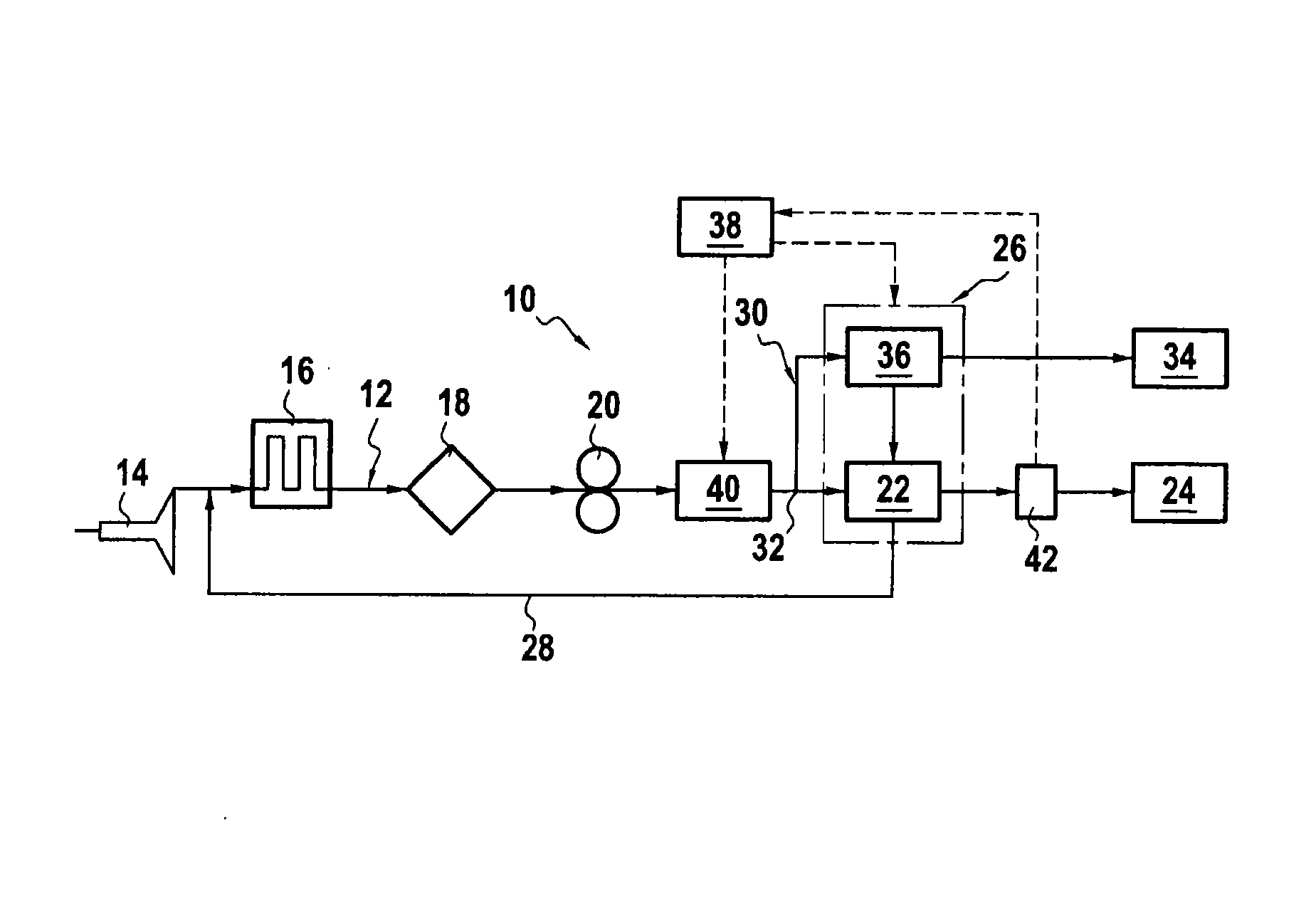
[0022]With reference to FIG. 1, the fuel circuit 10 for an aviation turbine engine comprises main fuel line 12 that is fitted in the fuel flow direction with a low pressure pump 14, a fuel / oil heat exchanger 16, a main fuel filter 18, and a so-called “high pressure” positive displacement pump 20. Naturally, a different arrangement of the equipment could be envisaged.

[0023]The upstream side of the low pressure pump 14 is connected to the fuel tank of the airplane (not shown in FIG. 1). The fuel / oil heat exchanger 16 serves to cool the oil for lubricating the engine by exchanging heat with the fuel via a heat exchange surface that separates these two fluids, and that also has the consequence of heating the fuel.

[0024]Downstream from the high pressure pump 20, the main fuel line 12 includes a metering member 22 for controlling the rate at which fuel is injected into the combustion chamber 24 of the engine via fuel injection systems (not shown). The fuel metering member 22 is controlled...


PUM


Abstract

A fuel circuit for an aviation turbine engine, the fuel circuit including: a main fuel line for feeding fuel to a combustion chamber of the engine and including a positive displacement pump; an auxiliary fuel line connected to the main fuel line at a junction situated downstream from the pump and serving to feed fuel to hydraulic actuators to control variable-geometry equipment of the engine, the auxiliary fuel line including electrohydraulic servo-valves upstream from each actuator; and a fuel pressure regulator valve arranged on the main fuel line downstream from the pump.

Description

BACKGROUND OF THE INVENTION[0001]The present invention relates to the general field of fuel flow in a turbine engine. The invention applies to any type of aviation turbine engine, and more particularly to airplane turbojets.[0002]In an aeroengine, it is common practice for fuel to be used not only for burning in the combustion chamber of the engine, but also as a hydraulic fluid in hydraulic actuators for controlling pieces of variable-geometry equipment of the engine (such as air bleak valves, and valves enabling the geometry of the compressor of the turbine engine to be adapted).[0003]For this purpose, the fuel circuit of a turbine engine typically comprises a main fuel line for feeding the combustion chamber of the engine with fuel, and an auxiliary fuel line connected to the main fuel line and serving to feed fuel to the hydraulic actuators in order to control pieces of variable-geometry equipment of the engine.[0004]The auxiliary fuel line for feeding the hydraulic actuators in...

Claims


Application Information

Patent Timeline
Patent Type & Authority Applications(United States)
IPC IPC(8): F02C7/22
CPCF02C7/22F02C7/222F02C7/224F02C7/236F02C9/26F02C9/263F02C9/28F05D2260/406F05D2270/303
Inventor POTEL, NICOLASGAMEIRO, SEBASTIEN
Owner SN DETUDE & DE CONSTR DE MOTEURS DAVIATION S N E C M A
Why Eureka
Try Eureka