Spun yarn winding device and spun yarn winding facility

Active Publication Date: 2013-10-31
TMT MACHINERY INC
View PDF1 Cites 4 Cited by
  • Summary
  • Abstract
  • Description
  • Claims
  • Application Information

AI Technical Summary

Benefits of technology

[0018]According to the spun yarn winding facility of the fourth preferred embodiment of the present invention, the spun yarn winding facility includes a combination of the plurality of spun yarn winding devices wherein the spun yarn winding devices are located on both the upper and lower stages in a state of a longitudinal layout, and the spun yarn winding facility is configured so that the yarns are fed to each of the traverse devices of the spun yarn winding devices from the upper portion. Since the spun yarn winding device is compacted in a vertical direction, even if the plurality of spun yarn winding devices is stacked in the up/down direction in multiple stages in a state of a longitudinal layout, the spun yarn winding facility is compact in a vertical direction. Particularly, the workability for the spun yarn winding devices which are located on the upper stage is improved. For this reason, without impairing the workability, the plurality of spun yarn winding devices can be stacked in the up/down direction in multiple stages in a state of a longitudinal layout. As a result, the space is effectively utilized.
[0019]According to the spun ya

Problems solved by technology

This saddle bag shape phenomenon may result in saddle bag shaped packages, and then, may disadvantageously prevent the line of yarns from being appropriately unwound from the packages during a post-process.
Because the above-mentioned conventional spun yarn winding device is provided with a movable portion projecting to an upper direction thereof, there is a problem that the device is unable to reduce the size of the spun yarn winding device in a vertical direction.
Furthermore, since the spun yarn winding device is large in

Method used


Image

  • Spun yarn winding device and spun yarn winding facility
  • Spun yarn winding device and spun yarn winding facility
  • Spun yarn winding device and spun yarn winding facility

Examples


embodiment 1

Preferred Embodiment 1

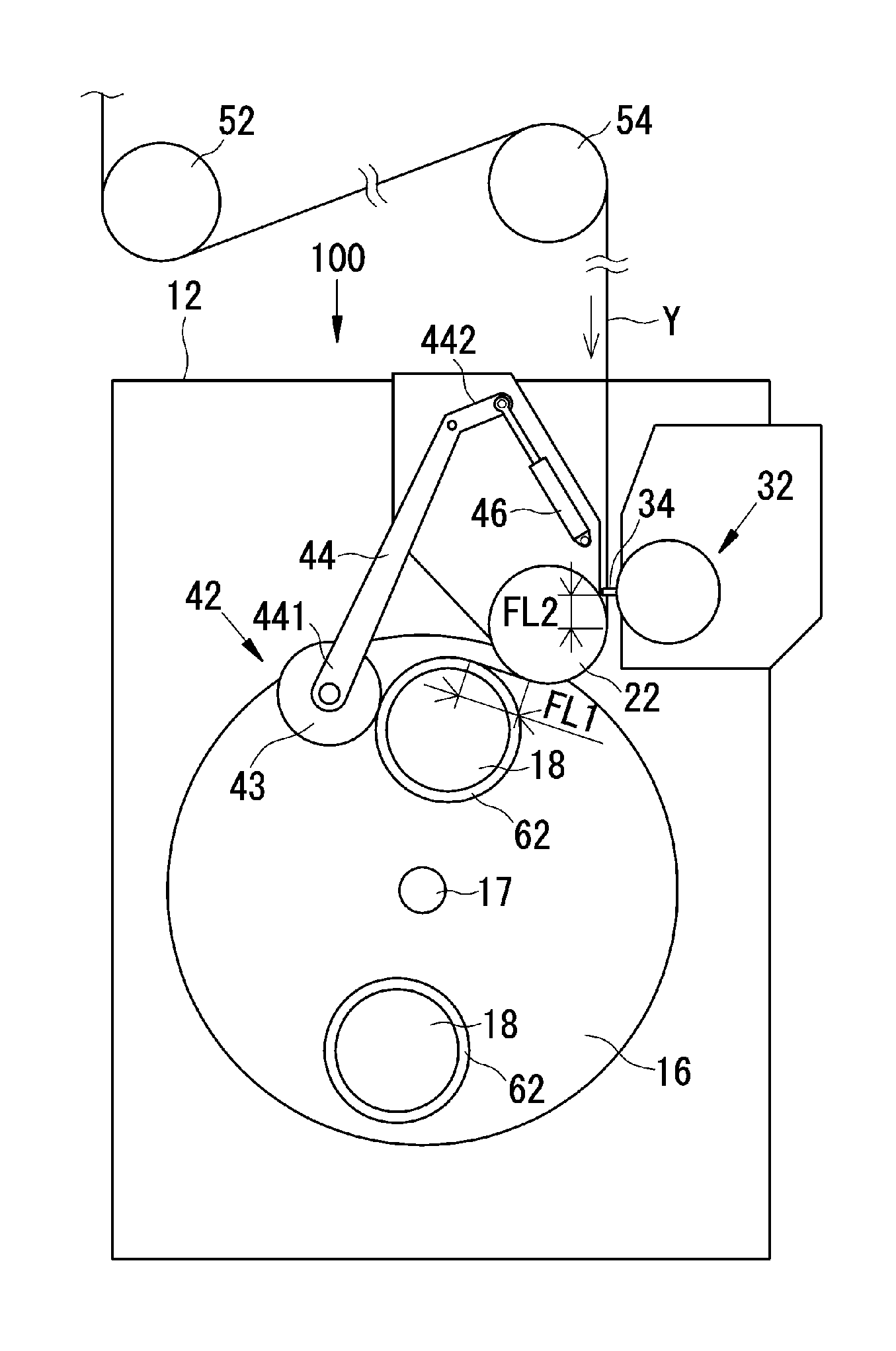
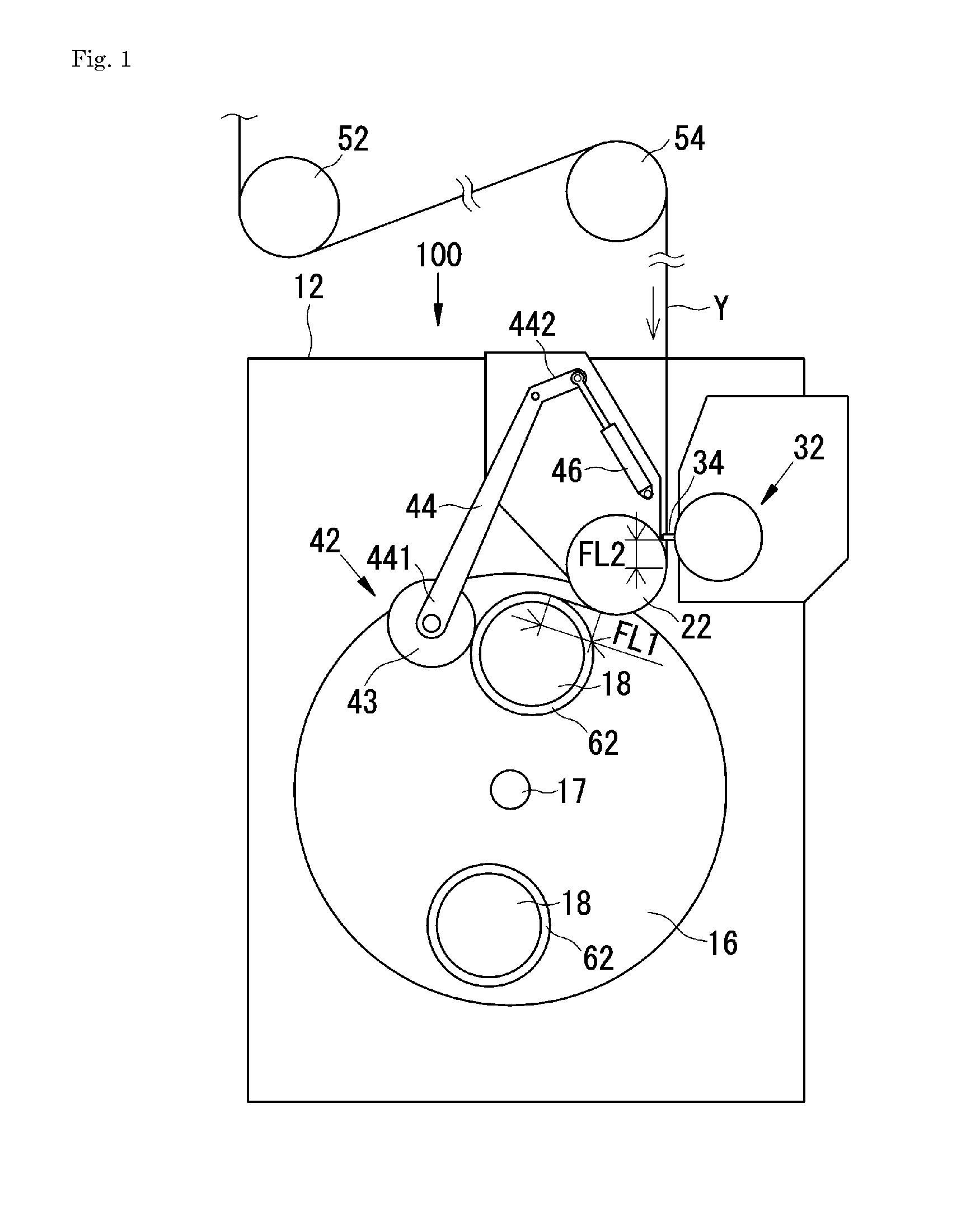
[0031]A spun yarn winding device 100 according to Preferred Embodiment 1 of the present invention will be described with reference to FIGS. 1 to 4.

[0032]As shown in FIG. 1, the spun yarn winding device 100 according to the present preferred embodiment is a device for forming packages 64 by winding the yarns Y onto tubes 62 traversing the yarns Y by a traverse device 32. The yarns Y are spun from a spinning device (not shown in the drawings) which is located at an upper position, and fed to the spun yarn winding device 100 through intermediaries of a roller 52, a roller 54 and the like. As indicated by an arrow, the traveling direction of the yarns Y is a direction from the upper positioned spinning device to the winding tubes 62.

[0033]Hereinafter, the yarns Y are explained as elastic yarns. However, the spun yarn winding device 100 can also wind yarns other than the elastic yarns. Although FIG. 1 shows the single spun yarn winding device 100, a spun yarn windin...

embodiment 2

Preferred Embodiment 2

[0053]Next, a spun yarn winding device 100 according to

[0054]Preferred Embodiment 2 of the present invention will be described with reference to FIGS. 5 to 7. Preferred Embodiment 2 differs significantly from Preferred Embodiment 1 in that the spun yarn winding device 100 according to Preferred Embodiment 2 corresponds to the spun yarn winding device 100 according to Preferred Embodiment 1 in which a bulge suppressing mechanism and a saddle bag shape collapsing mechanism are additionally provided. A detailed description of the same components as those of Preferred Embodiment 1 is omitted.

[0055]First of all, an explanation will be given of the bulge suppressing mechanism of the spun yarn winding device 100 according to the present preferred embodiment. Because yarn passages of elastic threads tends to be unstable as the winding speed of the yarns increases, high tension is applied to the elastic threads, and then, the elastic threads are wound onto winding bobbi...

embodiment 3

Preferred Embodiment 3

[0069]Next, a spun yarn winding facility 200 according to Preferred Embodiment 3 of the present invention is described with reference to FIG. 8. The spun yarn winding facility 200 of the present preferred embodiment preferably includes the combination of the plurality of spun yarn winding devices 100 which are described in Preferred Embodiment 1 wherein some of the plurality of spun yarn winding devices 100 are located on an upper stage and others of the plurality of spun yarn winding devices 100 are located on a lower stage. Detailed explanation with regard to the spun yarn winding device 100 is omitted.

[0070]As shown in FIG. 8, with regard to the spun yarn winding facility 200 of the present preferred embodiment, the spun yarn winding devices 100 are located on both the upper and lower stages in a state of a longitudinal layout. The yarns Y are spun at a spinning device (not shown in Figures) which is disposed at an upper portion and then fed to each spun yar...


PUM


Abstract

A spun yarn winding device includes a machine body; a turret; a feeding roller that is fixed to the machine body, is not in contact with winding bobbins, and feeds yarns to the winding bobbins at a speed equal to or faster than a winding speed; a traverse device fixed at an upstream side of an advance direction of the yarns relative to the feeding roller and which traverses the yarns; a peripheral speed detection unit that detects a peripheral speed of the winding bobbins; and a control unit that is arranged and programmed to perform a basic operation to maintain a free length of the yarns at a standard length by controlling a rotational angle of a turret during a yarn winding period, the free length of the yarns being located between the feeding roller and the winding bobbins.

Description

BACKGROUND OF THE INVENTION[0001]1. Field of the Invention[0002]The present invention relates to a spun yarn winding device and a spun yarn winding facility which winds spun yarns onto winding bobbins.[0003]2. Description of the Related Art[0004]Conventionally, a spun yarn winding device includes a traverse device with traverse guides that reciprocate in an axial direction of winding bobbins. A contact roller which is contacted by packages is provided on a lower side of the traverse device. As the yarns are being traversed and wound around the rotating winding bobbins into the packages so as to gradually increase in winding diameter, the position of the contact roller gradually rises corresponding to the increase in winding diameter of the packages. As such, the process for raising up the traverse device together with the contact roller corresponding to the increase in winding diameter of the packages so as to make constant the position of the contact roller and the traverse device ...

Claims


Application Information

Patent Timeline
IPC IPC(8): B65H54/28
CPCB65H54/28B65H54/385B65H54/52B65H54/72B65H54/74B65H61/005B65H63/082B65H67/048B65H2701/31B65H54/02B65H2701/319
Inventor HASHIMOTO, KINZO
Owner TMT MACHINERY INC
Why Eureka
Try Eureka