Air cooler system for gas turbine engines

a technology of air cooler and gas turbine engine, which is applied in the direction of machines/engines, efficient propulsion technologies, mechanical equipment, etc., can solve the problems of other issues affecting engine performan

Active Publication Date: 2013-11-07
PRATT & WHITNEY CANADA CORP
View PDF2 Cites 8 Cited by
  • Summary
  • Abstract
  • Description
  • Claims
  • Application Information

AI Technical Summary

Benefits of technology

[0004]In one aspect, the described subject matter provides an air cooler system for a gas turbine engine, comprising: an air cooler receiving a compressor air flow to pass therethrough, the air cooler disposed in an annular bypass air duct of the engine, the air cooler having an inlet opening to direct a flow of bypass air to the air cooler and an exit to direct exhaust air to the bypass air duct, the air cooler radially extending only part way into the bypass air duct to dispose a radial outer side of the cooler spaced apart from an outer wall of the bypass duct, a front wedge circumferentially aligned with the inlet opening and being disposed between the inlet opening and a radial inner edge of the cooler, and the front wedge being shaped to direct airflow between the radial inner edge of the cooler and the inlet opening to increase inlet pressure.

Problems solved by technology

However, a buffer air cooler disposed in a bypass air duct may cause flow resistance to the bypass air stream flowing through the bypass air duct and other issues affecting engine performance.

Method used


Image

  • Air cooler system for gas turbine engines
  • Air cooler system for gas turbine engines
  • Air cooler system for gas turbine engines

Examples


Embodiment Construction

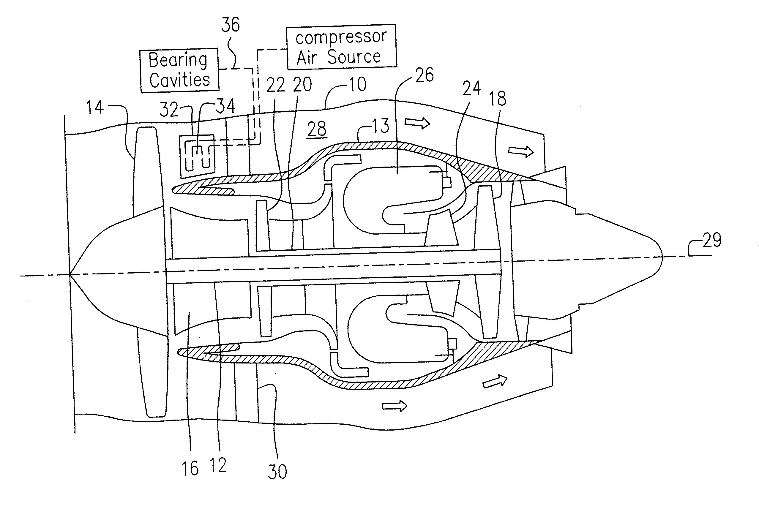
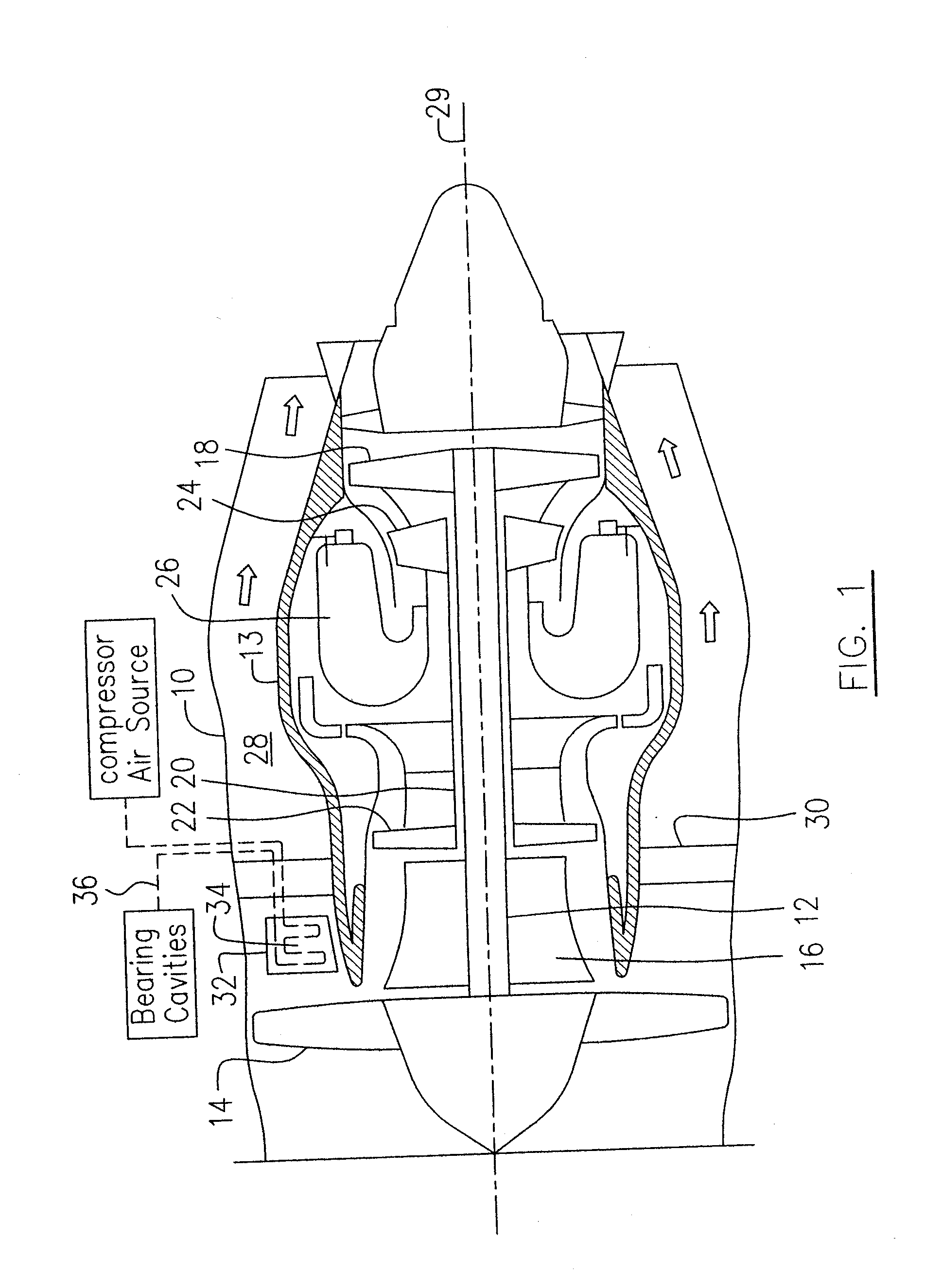
[0018]FIG. 1 illustrates an aircraft turbofan gas turbine engine presented as an example of the application of the described subject matter, including a housing or nacelle annular outer case 10, a annular core casing 13, a low pressure spool assembly seen generally at 12 which includes a fan assembly 14, a low pressure compressor assembly 16 and a low pressure turbine assembly 18, and a high pressure spool assembly seen generally at 20 which includes a high pressure compressor assembly 22 and a high pressure turbine assembly 24. The annular core casing 13 surrounds the low and high pressure spool assemblies 12 and 20 in order to define a main fluid path (not numbered) therethrough. In the main fluid path there is provided a combustor 26. An annular bypass air duct 28 is defined radially between the annular outer case 10 (the annular outer wall of the bypass duct) and the annular core casing 13 (as the annular inner wall of the bypass duct) for directing a main bypass air stream as i...


PUM


Abstract

A buffer air cooler system for gas turbine engines disposed in a bypass duct of the engine, includes a housing for containing the buffer air cooler therein and an inlet portion attached to the housing. In one embodiment, the inlet portion has a double-skin configuration in at least one region of a top, bottom and sides of the inlet portion.

Description

TECHNICAL FIELD[0001]The described subject matter relates generally to gas turbine engines, and more particularly to an improved buffer air cooler system for a gas turbine engine.BACKGROUND OF THE ART[0002]Aircraft gas turbofan engines operate at high temperature levels and therefore, turbine components and bearing cavities require efficient cooling, for example by air bled from the compressor of the engine. However, compressor air which is used to cool the turbine components and bearing cavities, has been heated by the compressor during the compression stage. Conventionally, an air-to-air heat exchanger is located in a bypass air duct of a turbofan gas turbine engine to capture a portion of a relatively cool bypass air flow to cool the relatively warmer compressor bleed air before the compressor bleed air is directed to various locations of the engine for cooling purposes. Such an air-to-air exchanger may be referred to as a buffer air cooler. However, a buffer air cooler disposed ...

Claims


Application Information

Patent Timeline
Patent Type & Authority Applications(United States)
IPC IPC(8): F02C6/08
CPCF02C7/14F05D2250/62F05D2260/213F05D2260/232F05D2250/51F02C6/08Y02T50/60F01D25/24F02C7/185F05D2220/32
Inventor MARINI, REMOGERMAIN, PATRICKVRLJES, LJUBISA
Owner PRATT & WHITNEY CANADA CORP
Why Eureka
Try Eureka