Bent axis hydraulic pump with centrifugal assist

a technology of hydraulic piston pump and axis, which is applied in the direction of machines/engines, liquid fuel engines, positive displacement liquid engines, etc., can solve the problems of prior art bent axis hydraulic piston pump being inadequate, and the pump not being able to run at the speed that it is capable, and achieves the effect of higher speeds

Active Publication Date: 2022-10-04
PARKER INTANGIBLES LLC
View PDF22 Cites 0 Cited by
  • Summary
  • Abstract
  • Description
  • Claims
  • Application Information

AI Technical Summary

Benefits of technology

[0004]The present invention provides a pump and motor assembly having an integral centrifugal pump with a bent axis hydraulic piston pump. The combination of the centrifugal pump and the bent axis hydraulic pump is advantageous in that the entire pump assembly may be run at higher speeds and pump more fluid as compared with conventional pumps.
[0005]In exemplary embodiments, the centrifugal pump includes an impeller driven by a drive motor. Hydraulic fluid is taken in through the centrifugal pump and rotation of the impeller causes the hydraulic fluid to have an increased inlet pressure, or inlet pressure boos to the bent axis pump. The hydraulic fluid being pumped is collected in the centrifugal pump chamber and routed to the inlet of the bent axis hydraulic pump which may run at relatively high speeds. The fluid is then pumped by the bent axis hydraulic pump and discharged into the system. The assembly may additionally use a wet-type electric drive motor having a stator and rotor that are submerged in the fluid being pumped. The pumped fluid may be routed from the impeller discharge to the motor housing to provide full and uniform lubrication and cooling of the motor components enabling the motor to run efficiently during the high-speed operation of the pump assembly.

Problems solved by technology

However, in many applications, the pumps are not able to run at speeds that they are capable of due to the cavitation that results at high revolutions per minute (RPMs).
These prior art bent axis hydraulic piston pumps may be inadequate for some applications in which it would be desirable to have a pump assembly that pumps larger amounts of fluid at higher pump speeds.

Method used


Image

  • Bent axis hydraulic pump with centrifugal assist
  • Bent axis hydraulic pump with centrifugal assist
  • Bent axis hydraulic pump with centrifugal assist

Examples


Embodiment Construction

[0038]The principles of the present invention may be suitable for use with pump assemblies used in high pressure applications. The pump assembly described herein may be suitable to provide pumping for stationary, mobile, and high vapor-pressure fluid applications. Examples of suitable applications may include oil and gas refining, offshore drilling, transportation refueling, aircraft refueling, mining, and chemical processing, hydraulic actuation and control.

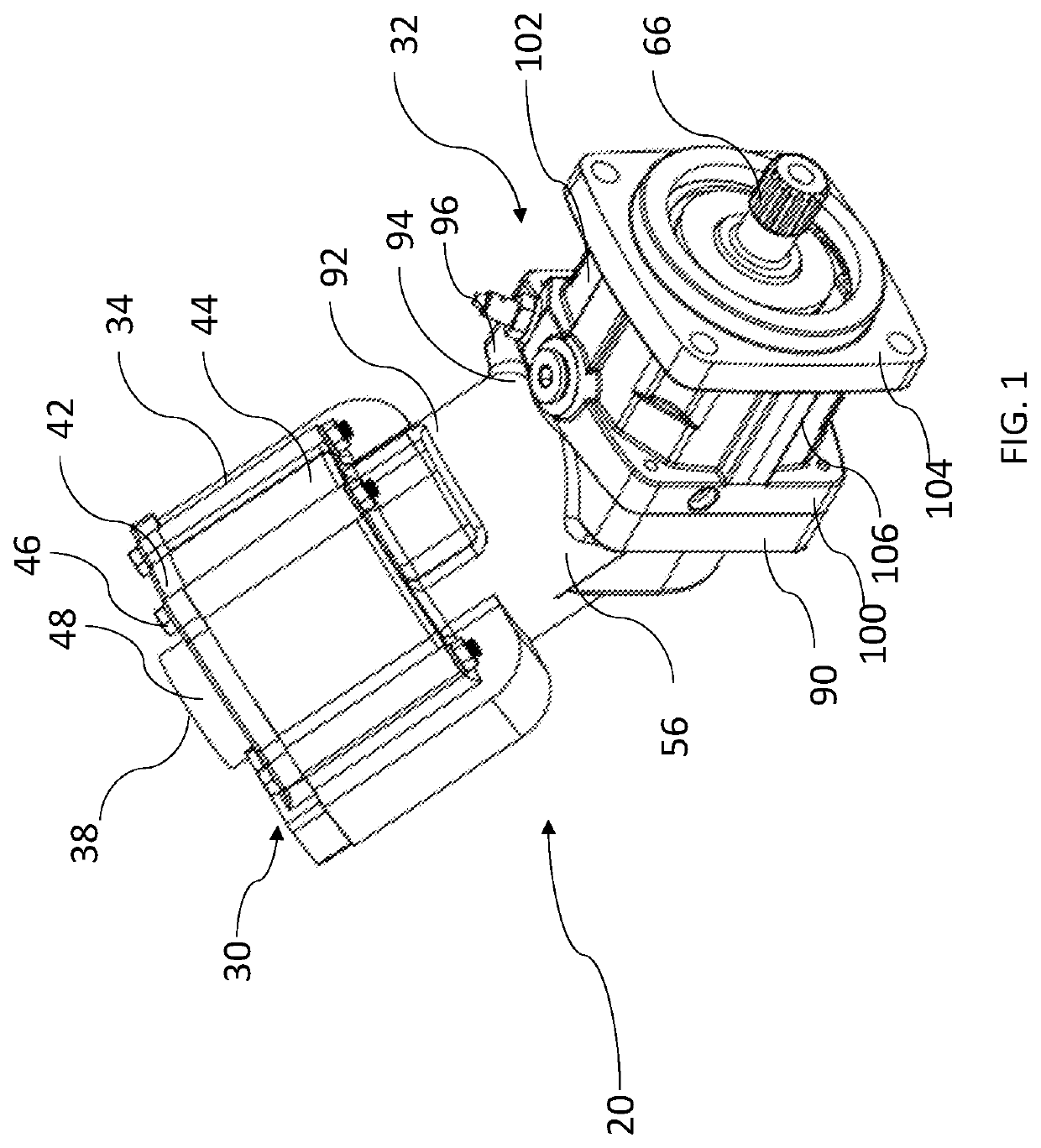
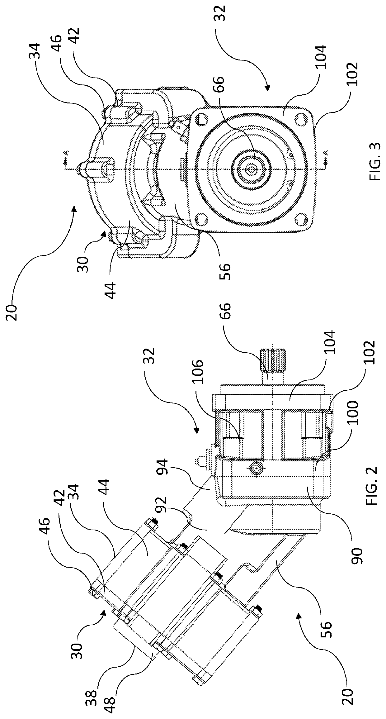
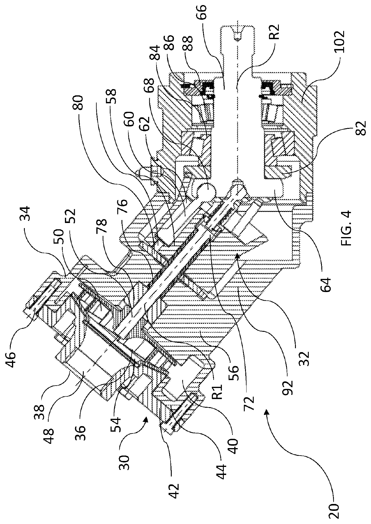
[0039]Referring first to FIGS. 1-10, a pump assembly 20 includes a centrifugal pump assembly 30 and a bent axis hydraulic pump assembly 32. The centrifugal pump assembly 30 includes a centrifugal pump housing 34 having an interior chamber 36, an inlet 38, and an outlet 40. The centrifugal pump housing 34 includes a volute chamber cover 42 that is secured to a main body 44 of the centrifugal pump housing 34. The main body 44 defines the interior chamber 36 and the volute chamber cover 42 closes the interior chamber 36. The outlet...


PUM


Abstract

A pump and motor assembly (20) includes a centrifugal pump (30), a bent axis hydraulic pump 58, and a wet-type drive motor (228). The motor has a rotor and a stator that are submerged in hydraulic fluid for full lubrication and cooling. A drive shaft 66 is driven by the motor. The centrifugal pump has a rotatable impeller (50) for pumping hydraulic fluid from an inlet (48) to the bent axis hydraulic pump. The centrifugal pump also pumps fluid to the motor for lubrication and cooling. The bent axis hydraulic pump pumps the fluid and discharges the fluid from the system. The centrifugal pump and the bent axis hydraulic pump are rotatable along a common rotational axis R1 that is angled relative to the rotational axis R2 of the drive shaft.

Description

[0001]This application is a national phase of International Application No. PCT / US2018 / 061240 filed Nov. 15, 2018 and published in the English language, which claims priority to U.S. Provisional Patent Application No. 62 / 589,678 filed Nov. 22, 2017, the entirety of both being hereby incorporated herein by reference.FIELD OF INVENTION[0002]The present invention relates to a bent axis hydraulic piston pump having a centrifugal pump that allows the bent axis piston pump to be operated at higher speeds to increase its flow performance.BACKGROUND[0003]Bent axis hydraulic piston pumps are known for their high pressure and high speed capability. However, in many applications, the pumps are not able to run at speeds that they are capable of due to the cavitation that results at high revolutions per minute (RPMs). These prior art bent axis hydraulic piston pumps may be inadequate for some applications in which it would be desirable to have a pump assembly that pumps larger amounts of fluid a...

Claims


Application Information

Patent Timeline
Patent Type & Authority Patents(United States)
IPC IPC(8): F04B1/20F04B23/14F04D25/16F04B23/10F04B1/24F04B1/2064
CPCF04B1/20F04B1/2064F04B1/24F04B23/106F04B23/14F04D25/16F04D13/12F04D29/426F04D29/22F04B1/2035F04B1/124F04B1/2042F05B2210/14F05D2240/14F05D2240/20F05B2240/20
Inventor CHU, YU-SEN J.
Owner PARKER INTANGIBLES LLC
Why Eureka
Try Eureka