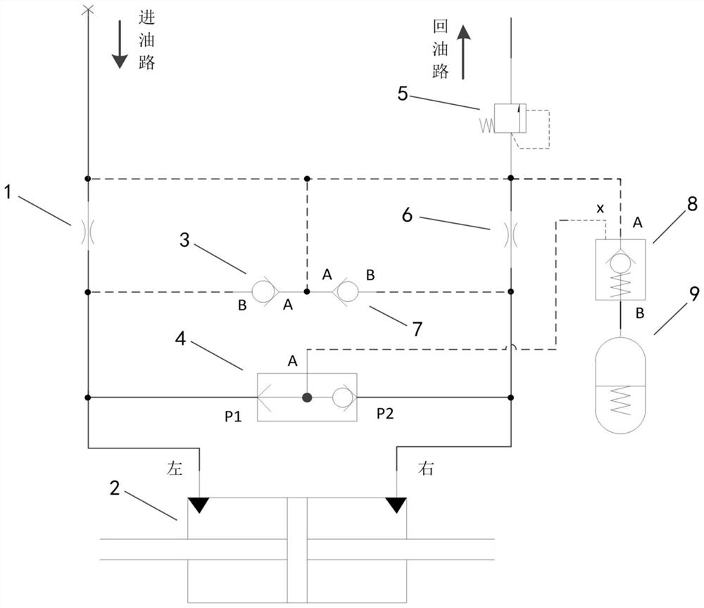
Low-leakage hydraulic anti-sway compensation circuit for aircraft nose wheel steering system

A technology of nose wheel steering and compensation circuit, which is applied to aircraft parts, landing gear, transportation and packaging, etc. It can solve the problems of increased weight and volume of the nose wheel steering system, oil leakage, and increased volume of the compensator, etc., to achieve Improved hydraulic flow and pressure holding time, effective low-leakage hydraulic sway compensation, and reduced hydraulic flow

Active Publication Date: 2021-06-15
COMAC +1
View PDF0 Cites 0 Cited by
  • Summary
  • Abstract
  • Description
  • Claims
  • Application Information

AI Technical Summary

Problems solved by technology

[0004] Although the traditional hydraulic compensation method can realize hydraulic pressure reduction and oil and pressure compensation during the reduction process, it has the following disadvantages: when the hydraulic reduction circuit is not working, because the compensator is always connected to the reduction circuit, the oil stored in the compensator The liquid leaks continuously through the unloading valve at the oil return, the flow in the compensator decreases continuously, and the pressure gradually decreases
For the aircraft nose wheel steering system, the sway reduction circuit has no pressure supply during the long-term flight of the aircraft, and the oil stored in the compensator needs to increase according to the increase in the no pressure supply time, resulting in an increase in the volume of the compensator, and the weight and weight of the nose wheel steering system. The volume increases accordingly, and the weight of the aircraft increases

Method used


Image

  • Low-leakage hydraulic anti-sway compensation circuit for aircraft nose wheel steering system

Examples


Embodiment Construction

[0042] Specific implementations of the present invention will be described below. It should be noted that in the process of specific descriptions of these implementations, for the sake of concise description, it is impossible for this specification to describe all the features of the actual implementations in detail. It should be understood that, in the actual implementation process of any embodiment, just like in the process of any engineering project or design project, in order to achieve the developer's specific goals and to meet system-related or business-related constraints, Often a variety of specific decisions are made, and this can vary from one implementation to another. In addition, it will be appreciated that while such development efforts may be complex and lengthy, the technology disclosed in this disclosure will be Some design, manufacturing or production changes based on the content are just conventional technical means, and should not be interpreted as insuffic...


PUM


Abstract

The invention relates to a low-leakage hydraulic pressure reduction compensation circuit for an aircraft nose wheel steering system. The hydraulic sway compensation circuit includes a turning actuator, a pressure sensitive device, an unloading valve, an anti-leakage device, and a compensator; hydraulic flow and hydraulic pressure are stored in the compensator, and the anti-leakage device is arranged at the outlet of the compensator, and the unloading valve The unloading valve is set at the oil return circuit of the aircraft hydraulic system. Under the action of the back pressure generated by the unloading valve, the hydraulic flow enters the compensator through the anti-leakage device, and forms the required hydraulic pressure under the action of the compensator. The pressure sensitive device It is arranged at the left and right chambers of the turning actuator. When the pressure in at least one chamber of the turning actuator exceeds the pressure threshold, the pressure in the chamber controls the opening of the anti-leakage device through the pressure sensitive device, so that the hydraulic pressure in the compensator flow out of the compensator. The hydraulic anti-sway compensating circuit can have the following beneficial technical effects: reducing the leakage of the compensator of the hydraulic anti-swaying circuit and reducing the hydraulic flow required to be stored by the compensator.

Description

technical field [0001] The invention relates to a low-leakage hydraulic pressure reduction compensation circuit for an aircraft front wheel steering system, and belongs to the technical field of aircraft hydraulic control. Background technique [0002] The hydraulic anti-swing reduction of the front wheel of the aircraft quickly attenuates the front wheel shimmy caused by the external load through the damping effect of the throttle valve. The shimmy circuit supplements flow and pressure for the shimmy circuit by setting a compensator. Since the hydraulic energy system no longer provides hydraulic pressure and flow to the nose wheel steering system during aircraft flight, in order to ensure that the hydraulic swing reduction is in the event of hydraulic system failure, the aircraft still has the nose wheel steering hydraulic swing reduction capability during landing, and the compensator needs to To ensure that the aircraft has the pressure and flow required to compensate the...

Claims


Application Information

Patent Timeline
Patent Type & Authority Patents(China)
IPC IPC(8): B64C25/50
CPCB64C25/50B64C25/505
Inventor 姜逸民陈勇陈文杰孟庆堂任碧诗职光伸
Owner COMAC
Why Eureka
Try Eureka