Glass substrate laser cutting device with real-time breaking detecting function and glass substrate breakage detecting method thereof

a laser cutting device and glass substrate technology, applied in the direction of manufacturing tools, instruments, transportation and packaging, etc., can solve the problems of critical damage in the laser cutting device, the damage of the laser optical system and the optical path caused by the damage of the glass substrate may not be basically prevented, and the contamination of the optical system and the optical path, so as to prevent critical damage, improve the yield rate of the laser cutting system, and improve the effect of safety in operation

Active Publication Date: 2013-11-07
SAMSUNG CORNING PRECISION MATERIALS CO LTD
View PDF7 Cites 21 Cited by
  • Summary
  • Abstract
  • Description
  • Claims
  • Application Information

AI Technical Summary

Benefits of technology

[0014]According to the glass substrate laser cutting device with the real-time breakage detecting function and the glass substrate breakage detecting method thereof in accordance with the invention, since it is possible to monitor the damage of the glass substrate in all cases and occurring in all procedures of the laser cutting process not only when conveying the glass substrate but also when performing the glass substrate cutting process, it is possible to previously prevent critical damage from occurring due to contamination of an optical system and an optical path of the laser cutting process in the case where the damage is not detected. Accordingly, there is an excellent advantage in that not only the performance in the yield rate of the laser cutting system but also the safety in the operation may be remarkably improved.
[0015]Furthermore, since the breakage of the glass substrate may be detected in real-time by directly using the vacuum suction pressure essentially necessary for cutting the glass substrate, it is possible to manufacture the glass substrate laser cutting device very economically without an increase in cost. Accordingly, there is an advantage in that the industrial applicability is high.
[0016]Furthermore, since the vacuum absorbing grooves detecting the breakage of the glass while realizing the vacuum suction of the glass substrate are densely formed in a lattice shape, a change in the vacuum pressure easily occurs even when breakage is present on any point of the glass substrate suctioned and fixed to the working bar or the breakage is minute. Accordingly, there is a noticeable advantage in that the performance and the accuracy of detecting the breakage of the glass substrate may be further improved.

Problems solved by technology

However, since the sheet or the pad is formed of a combustible material, soot may be generated during combustion when the surface is irradiated with the laser beam, so that the optical system and the optical path are contaminated, which causes critical damage in the laser cutting device.
However, in many cases, there is a limitation in that the damage of the laser optical system and the optical path caused by the damage of the glass substrate may not be basically prevented only by the existing glass substrate breakage detecting method.
That is, even when the glass substrate state of both sides to be cut by a laser is normal based on a time point at which the glass substrate is conveyed, if the breakage portions of the other both sides which are not detected upon aligning the glass substrate for the laser cutting process increase in size and the combustible material below the glass substrate is exposed, there is a problem in that soot generated during the laser cutting contaminates the optical system and the optical path.

Method used


Image

  • Glass substrate laser cutting device with real-time breaking detecting function and glass substrate breakage detecting method thereof
  • Glass substrate laser cutting device with real-time breaking detecting function and glass substrate breakage detecting method thereof
  • Glass substrate laser cutting device with real-time breaking detecting function and glass substrate breakage detecting method thereof

Examples


Embodiment Construction

[0026]Reference will now be made in detail to the present embodiments of the present invention, examples of which are illustrated in the accompanying drawings, wherein like reference numerals refer to the like elements throughout. The embodiments are described below in order to explain the present invention by referring to the figures.

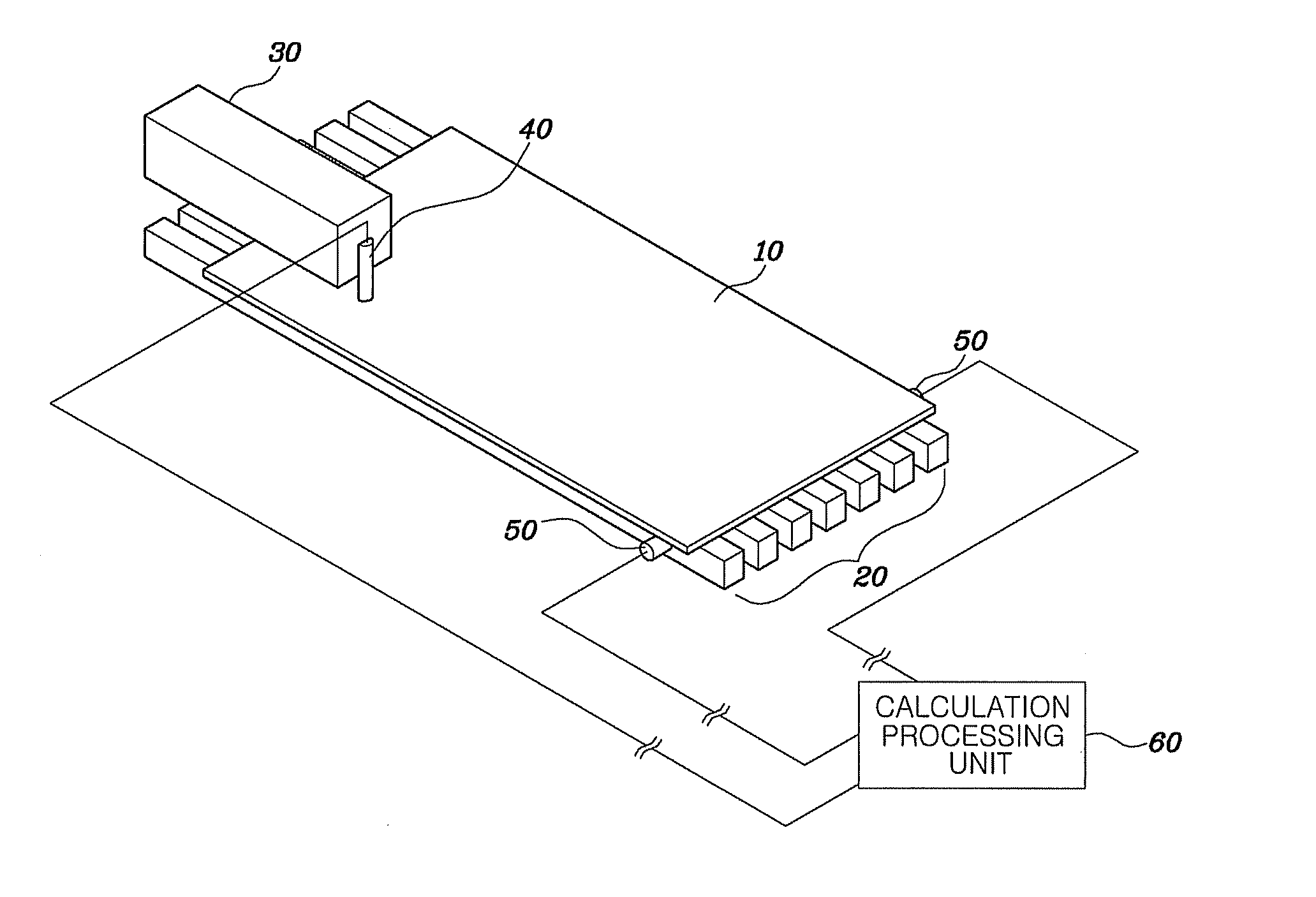
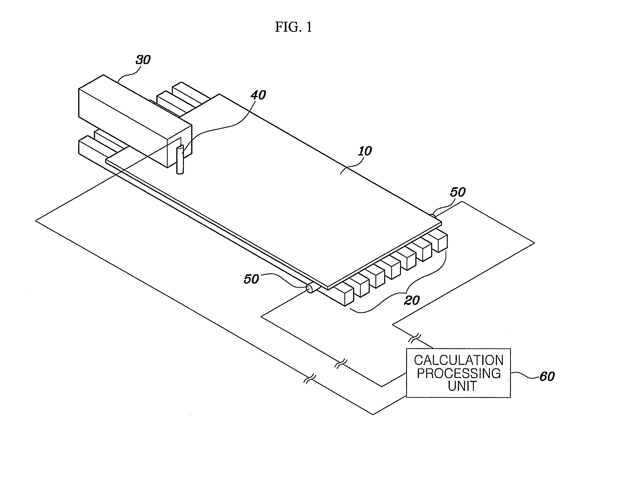
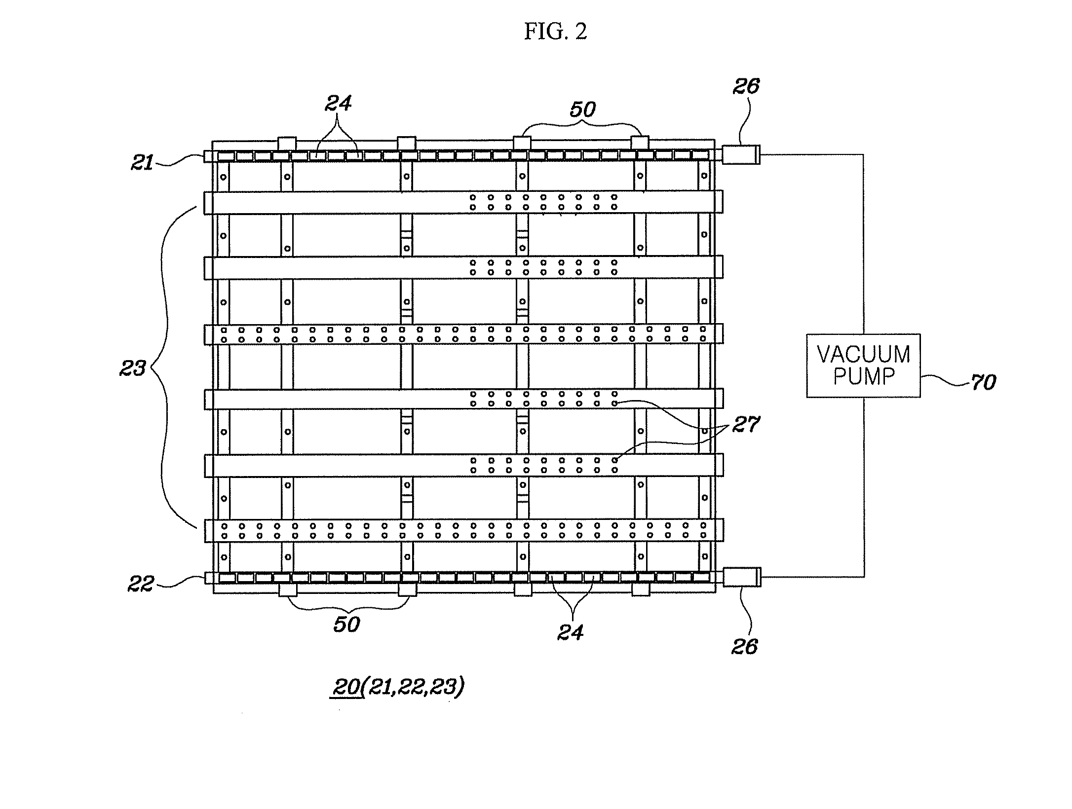
[0027]The invention discloses a technology capable of monitoring breakage of a glass substrate in real-time during a process of cutting the glass substrate by organically using a vacuum suction pressure for fixing the glass substrate and a laser cutter for cutting the glass substrate.

[0028]Hereinafter, preferred embodiments, advantages, and features of the invention will be described in detail by referring to the accompanying drawings.

[0029]Prior to description, the term of a ‘real-time glass substrate breakage detecting function’ used in the invention indicates a function of immediately detecting occurrence of breakage from a time point right before c...


PUM

PropertyMeasurementUnit
vacuum pressureaaaaaaaaaa
threshold pressureaaaaaaaaaa
areaaaaaaaaaaa

Abstract

A glass substrate laser cutting device according to the invention includes: a working table that has a plurality of vacuum absorbing grooves; a laser cutter; a pressure sensor that measures a pressure sensor when suctioning the glass substrate in a vacuum state; a calculation processing unit that compares the vacuum pressure measured by the pressure sensor with a predetermined threshold pressure and determines whether the glass substrate is broken; a laser cutter that includes a leaser head moving along the cutting direction of the glass substrate and emitting a laser beam; and an optical sensor that is attached to the laser head so as to move together and is disposed at a point in front of the laser beam emitted to the outside so as to detect the breakage of the glass substrate.

Description

CROSS-REFERENCE TO RELATED APPLICATIONS[0001]This application claims the benefit of Korean Patent Application No. 10-2012-0047395, filed on May 4, 2012, in the Korean Intellectual Property Office, the disclosure of which is incorporated herein by reference.BACKGROUND OF THE INVENTION[0002]1. Field of the Invention[0003]The present invention relates to a glass substrate laser cutting device and a glass substrate breakage detecting method, and more particularly, relates to a glass substrate laser cutting device with a real-time breakage detecting function capable of monitoring breakage of a glass substrate in real-time during a glass substrate cutting process by organically using a vacuum suction pressure and a laser cutter for cutting the glass substrate.[0004]2. Description of the Related Art[0005]In a process of cutting a glass substrate using a laser beam, it is very important to maintain flatness of a glass substrate which is a workpiece due to the nature of the process. Accordin...

Claims


Application Information

Patent Timeline
Patent Type & Authority Applications(United States)
IPC IPC(8): C03B33/09
CPCB65G2249/04B65G2249/045C03B33/033C03B33/037C03B33/091G01N21/958B23K26/38C03B33/02C03B33/09G01N21/00C03B33/03C03B33/102
Inventor ROH, HYUNG-SANGKOO, JA-YONGKIM, SUNG CHEALPARK, WON-KYULEE, CHANG-HA
Owner SAMSUNG CORNING PRECISION MATERIALS CO LTD
Why Eureka
Try Eureka