Radiation Detector System and Method

a radiation detector and detector technology, applied in the field of radiation detection systems and methods, can solve the problems of reducing production yield, increasing production costs, and increasing overall assembly time, and achieves the effect of reducing field maintenance costs and easy and rapid field replacemen

Active Publication Date: 2013-11-07
CANBERRA IND INC
View PDF6 Cites 1 Cited by
  • Summary
  • Abstract
  • Description
  • Claims
  • Application Information

AI Technical Summary

Benefits of technology

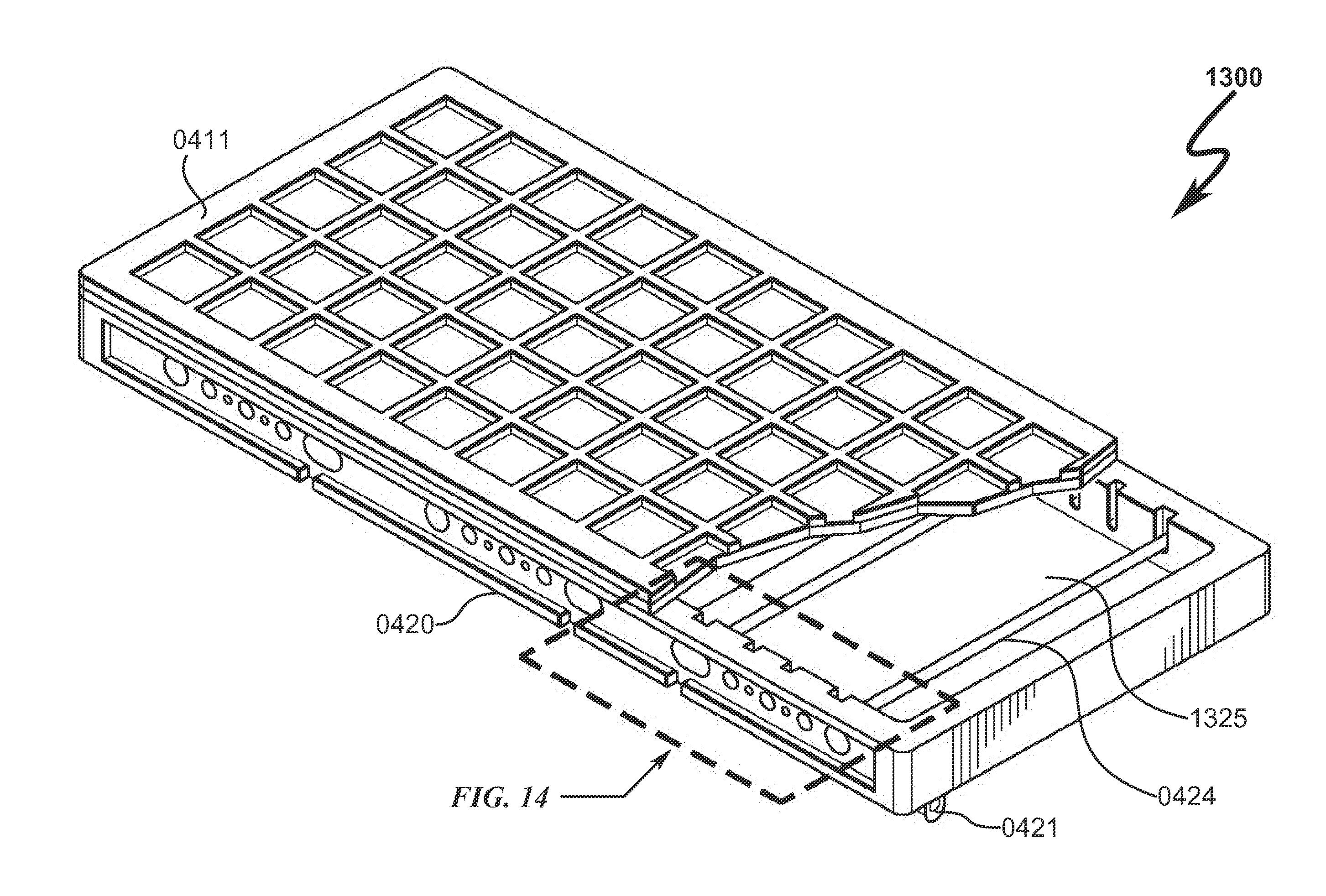
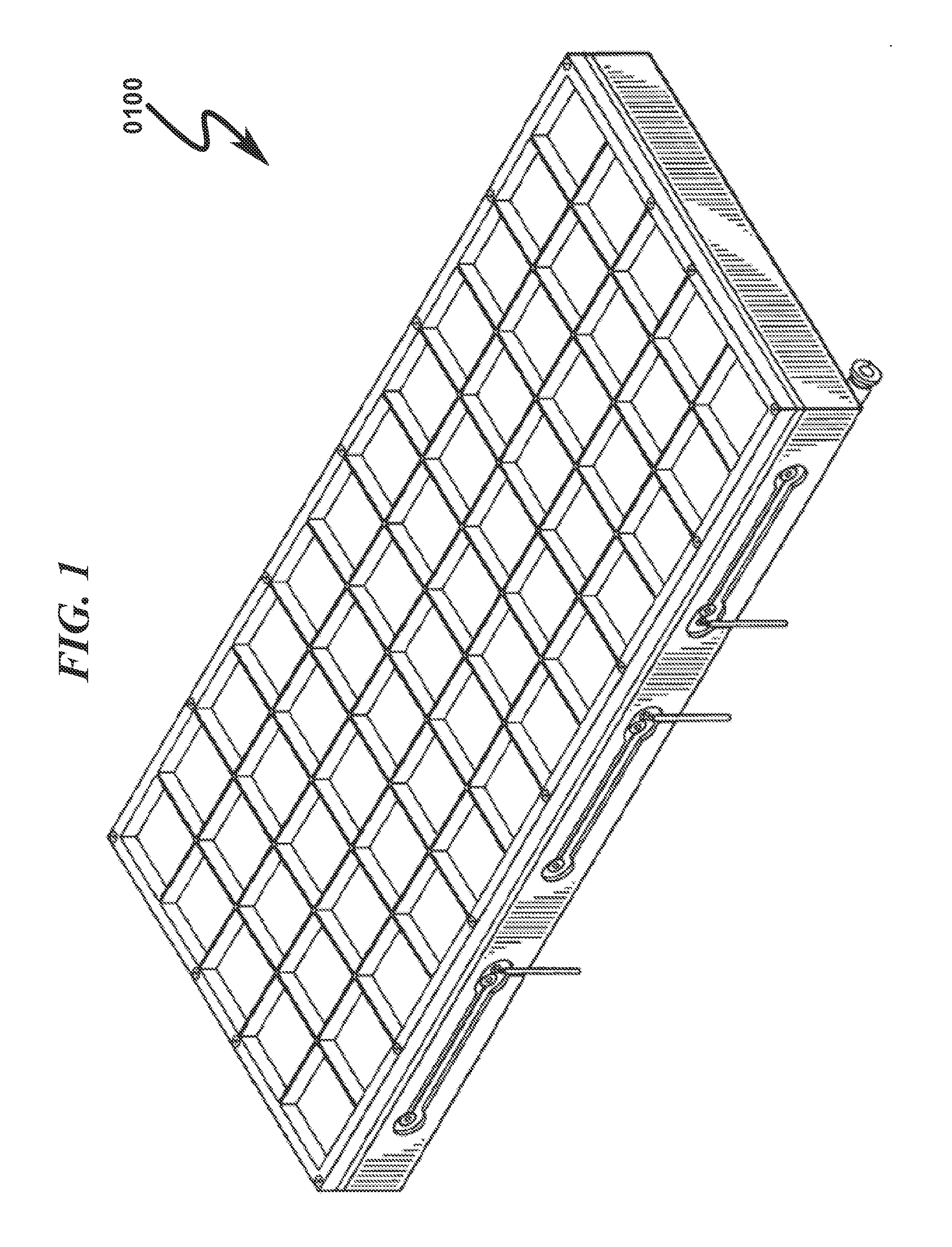
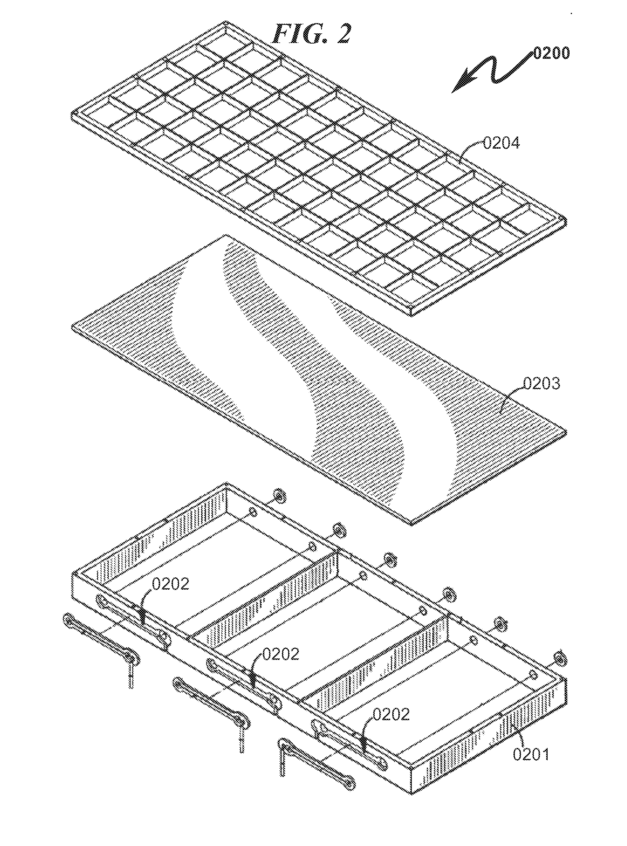
[0018](1) Provide for a radiation detector system and method that permits easy assembly using a “snap on” type of attachment between the detector body and the detector window.
[0020](3) Provide for a radiation detector system and method that is significantly lower in cost as compared to the prior art.
[0021](4) Provide for a radiation detector system and method that provides for easy and rapid field replacement of damaged detector windows, thus reducing field maintenance costs.
[0027]A “snap on” means to easily attach / detach the detector window assembly from the detector body without any gas leakage, incorporating a gasket or another sealing means.
[0028]A locking mechanism to hold the detector window assembly in place, while simultaneously allowing it to be pried apart from the detector body for easy field replacement of the detector window.
[0029]Material selection (optimally plastic) with sufficient rigidity to prevent deformation of both detector window and detector body.

Problems solved by technology

However, the prior art as detailed above suffers from the following deficiencies:A typical implementation of this prior art radiation detector requires a laser cut stainless steel grill frame that is very expensive to manufacture and prone to have sharp edges, a potential cause of pinhole failures in the MYLAR® film.The use of multiple screws (18) to attach the stainless steel window to the aluminum body significantly adds to the production cost.Gas feed-thrus (6 on one side and 3 on the opposite side) are individually installed and epoxy sealed onto the aluminum body, a time consuming manufacturing process.In addition to extra labor, the epoxy sealant requires curing at elevated temperature which adds to the overall assembly time.Leaks may occur in this structure, resulting in reduced production yield and requiring assembly rework.Replacing the window in the field is cumbersome, and requires the application of sealant, resulting in an unwanted added cost to the end-user customer.Gas leakages in this unit operationally increase costs and add to the carbon footprint of the overall system.
While some of the prior art may teach some solutions to several of these problems, the core issues of simultaneous cost reduction and reliability improvement in these prior art systems has not been addressed.

Method used


Image

  • Radiation Detector System and Method
  • Radiation Detector System and Method
  • Radiation Detector System and Method

Examples


Embodiment Construction

[0051]While this invention is susceptible of embodiment in many different forms, there is shown in the drawings and will herein be described in detailed preferred embodiment of the invention with the understanding that the present disclosure is to be considered as an exemplification of the principles of the invention and is not intended to limit the broad aspect of the invention to the embodiment illustrated.

[0052]The numerous innovative teachings of the present application will be described with particular reference to the presently preferred embodiment, wherein these innovative teachings are advantageously applied to the particular problems of a RADIATION DETECTOR SYSTEM AND METHOD. However, it should be understood that this embodiment is only one example of the many advantageous uses of the innovative teachings herein. In general, statements made in the specification of the present application do not necessarily limit any of the various claimed inventions. Moreover, some statemen...


PUM

PropertyMeasurementUnit
tensionaaaaaaaaaa
electric fieldaaaaaaaaaa
insulatingaaaaaaaaaa

Abstract

A radiation detector system and method that significantly reduces the cost of conventionally constructed radiation detectors is disclosed. The disclosed system generally comprises an injection molded detector body incorporating plastic material with embedded feed-thrus that are encapsulated within the detector body. This detector body is mated to a detector window assembly using a gasket or other means of sealing to inhibit gas leakage. The mating methodology between the detector body and the detector window assembly is by means of plastic snap-on tabs in these structures that permit semi-permanent mating while also allowing the structures to be easily disassembled for repair and maintenance. The present invention system / method permits a significant hardware cost reduction as compared to conventional prior art radiation detector construction methodologies.

Description

CROSS REFERENCE TO RELATED APPLICATIONS[0001]Not ApplicablePARTIAL WAIVER OF COPYRIGHT[0002]All of the material in this patent application is subject to copyright protection under the copyright laws of the United States and of other countries. As of the first effective filing date of the present application, this material is protected as unpublished material.[0003]However, permission to copy this material is hereby granted to the extent that the copyright owner has no objection to the facsimile reproduction by anyone of the patent documentation or patent disclosure, as it appears in the United States Patent and Trademark Office patent file or records, but otherwise reserves all copyright rights whatsoever.STATEMENT REGARDING FEDERALLY SPONSORED RESEARCH OR DEVELOPMENT[0004]Not ApplicableREFERENCE TO A MICROFICHE APPENDIX[0005]Not ApplicableFIELD OF THE INVENTION[0006]The present invention generally relates to systems and methods for the detection of radiation, more particularly, but...

Claims


Application Information

Patent Timeline
Patent Type & Authority Applications(United States)
IPC IPC(8): G01T1/18
CPCH01J47/002B29C45/14336B29C45/14426B29C45/14639
Inventor MAHDESSIAN, ABRAHAMBOGORODZKI, ADAM GREGORY
Owner CANBERRA IND INC
Why Eureka
Try Eureka