Image forming apparatus
a technology forming machine, which is applied in the direction of electrographic process apparatus, visual presentation, instruments, etc., can solve the problems of increased cost and size, inability to execute double-sided printing operation, and complicated overall mechanism configuration of image forming apparatus, etc., to achieve stable print performance and improve productivity
- Summary
- Abstract
- Description
- Claims
- Application Information
AI Technical Summary
Benefits of technology
Problems solved by technology
Method used
Image
Examples
first embodiment
[0026](Image Forming Apparatus)
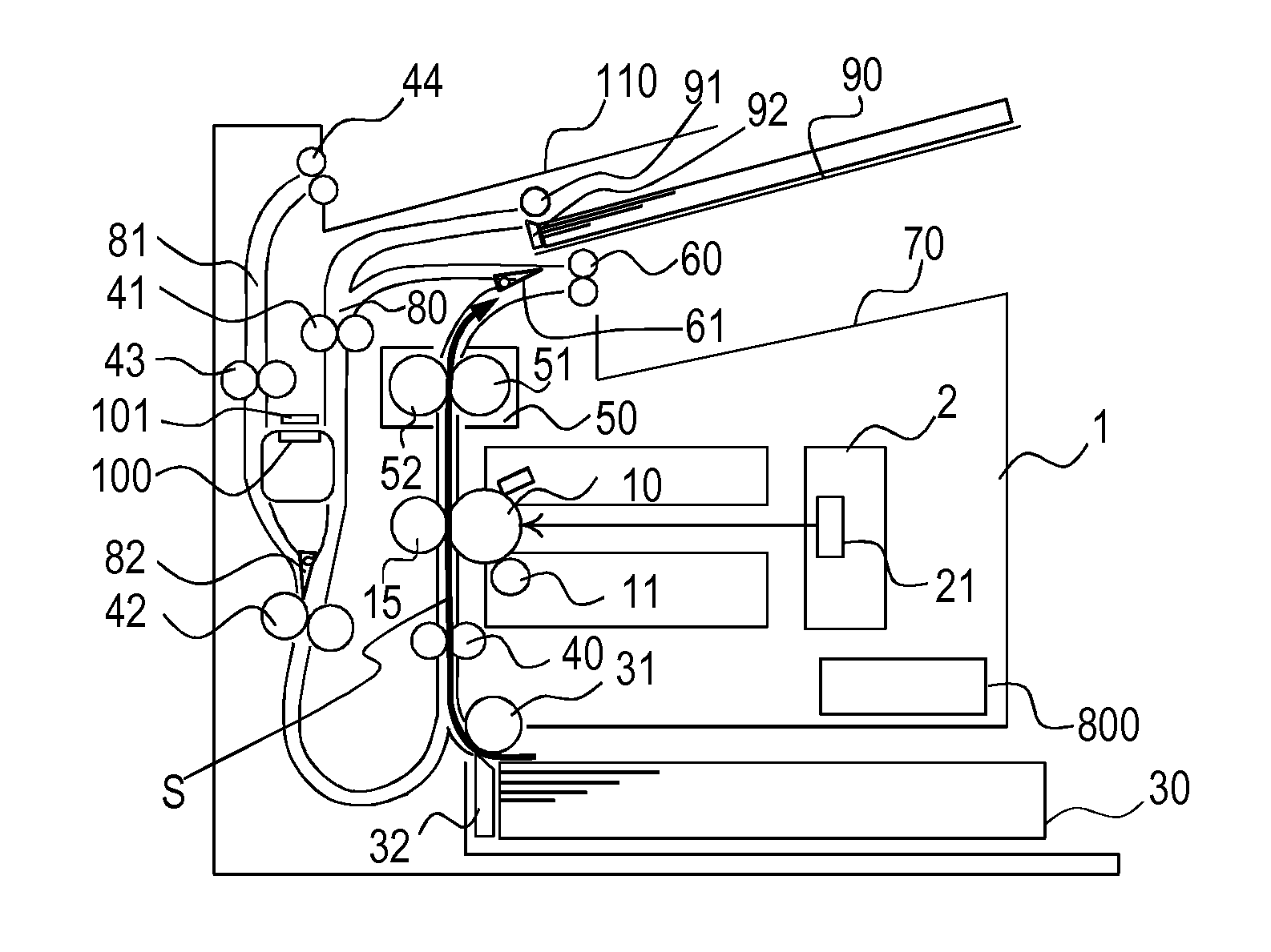
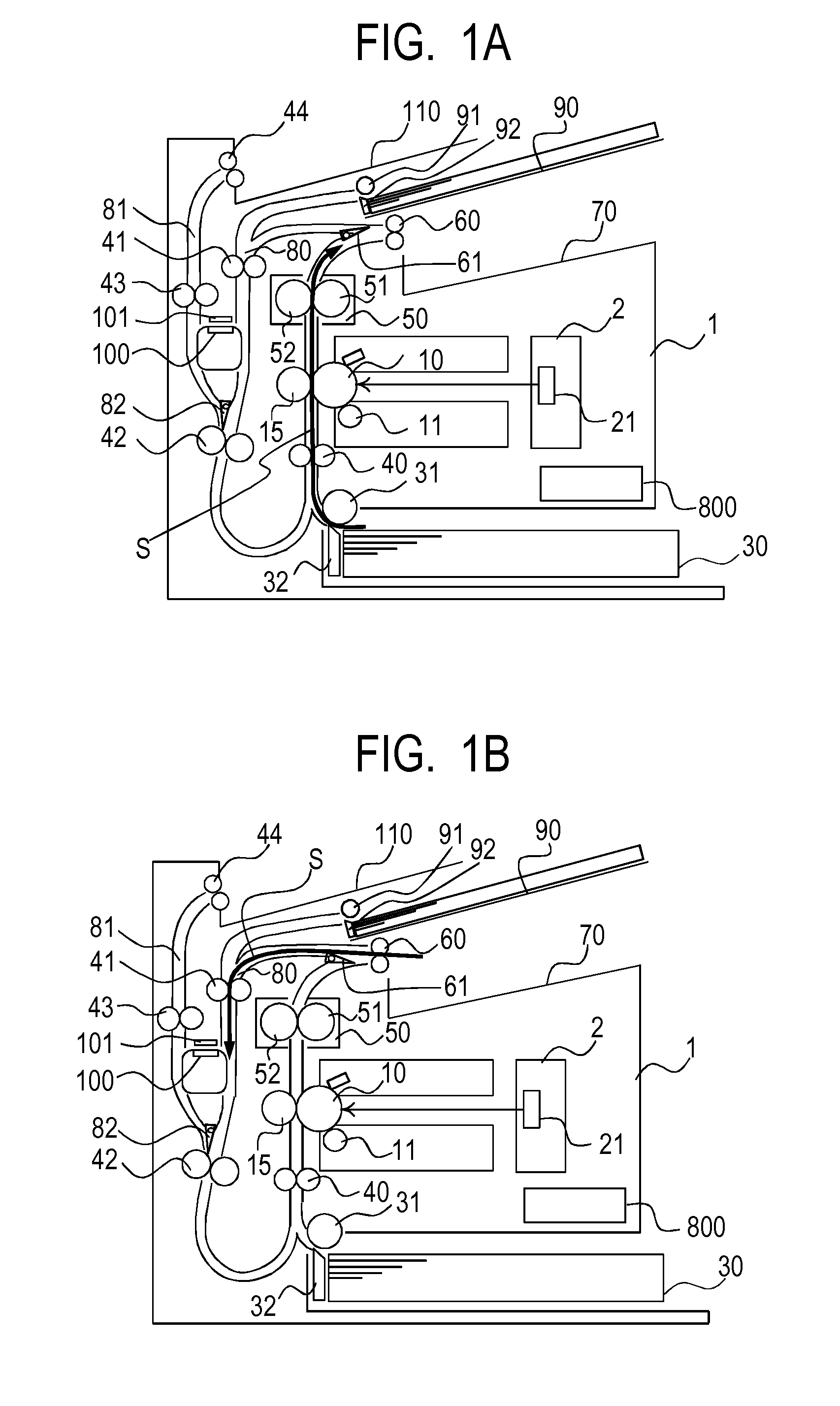
[0027]FIG. 1A is a schematic diagram of an image forming apparatus 1 according to a first embodiment of the present invention. The image forming apparatus 1 includes, at the center thereof, a rotatable photosensitive drum 10 serving as an image bearing member, and a developing roller 11 provided to be along and come contact with the photosensitive drum 10 and configured to rotate while carrying toner on the developing roller 11. When a print signal is received, a light emitting section 21 of an optical unit 2 irradiates a surface of the rotating photosensitive drum 10 with laser light. An electrostatic latent image is formed on the surface of the photosensitive drum 10 that is irradiated with the laser light. When the toner carried on the rotating developing roller 11 is fed to the electrostatic latent image on the surface of the photosensitive drum 10, a toner image is formed on the surface of the photosensitive drum 10.
[0028]On the other hand, record...
second embodiment
[0062]In the second embodiment, the basic configuration of the image forming apparatus is the same as that in the first embodiment except for the control of the rotation direction of the original read unit 100, such as the processing in S1706 of FIG. 5. The same applies to the embodiments to be described later. This embodiment is directed to a case where the original read operation of the original read unit is not performed and the double-sided print operation is performed on the recording material.
[0063](Double-Sided Print Operation without Original Read Operation)
[0064]Referring to FIG. 6, control of the rotation direction of the original read unit 100 in the case of performing only the image forming operation without using the original read unit 100 is described. In response to a double-sided print command received from the host computer (not shown), the recording material S is first conveyed to the transfer roller 15 by the conveyance roller pair 40. Then, a toner image is trans...
third embodiment
[0068]The third embodiment is directed to a case where the single-sided read operation is performed on the originals and the double-sided print operation is performed on the recording material.
[0069](Single-Sided Read Operation and Double-Sided Print Operation)
[0070]FIG. 7A illustrates a state in which the information on the first surface of the original G is acquired as in the processing in S1709 of FIG. 5. In this case, the original read unit 100 is located at the second read position facing the double-sided conveyance path 80. Subsequently, as illustrated in FIG. 7B, the original G is switched back through use of the conveyance roller pair 42, and is conveyed to the conveyance roller pair 43 and the conveyance roller pair 44. At the same time, the recording material S and the second original G2 start to be conveyed through use of the CST pickup roller 31 and the original pickup roller 91, respectively. As illustrated in FIG. 7C, during a period in which the read operation for the...
PUM
 Abstract
Description
Claims
Application Information
 - R&D
- Intellectual Property
- Life Sciences
- Materials
- Tech Scout
- Unparalleled Data Quality
- Higher Quality Content
- 60% Fewer Hallucinations
Browse by: Latest US Patents, China's latest patents, Technical Efficacy Thesaurus, Application Domain, Technology Topic, Popular Technical Reports.
© 2025 PatSnap. All rights reserved.Legal|Privacy policy|Modern Slavery Act Transparency Statement|Sitemap|About US| Contact US: help@patsnap.com


