Decorative monolithic, functionally bonded composite surface overlayment system and application process

a functionally bonded, composite surface technology, applied in the direction of synthetic resin layered products, flooring, packaging, etc., can solve the problems of complex application process, high labor and time consumption, and the use of exotic woods or certain marbles or granites is not without problems, so as to achieve the enhancement of interior/exterior flooring surface overlay, countertops and other horizontal surfaces

Inactive Publication Date: 2013-11-07
FINDEX COM
View PDF5 Cites 23 Cited by
  • Summary
  • Abstract
  • Description
  • Claims
  • Application Information

AI Technical Summary

Benefits of technology

[0011]The present invention describes a decorative surface covering comprising a plurality of component layers, structural and / or chemical, chemically bonded together to form a unique single unit, decorative monolithic functionally bonded system, referred to generally herein as a functionally bonded system. While the individual components have various properties, the chemical bonding of one layer to an adjacent layer above and / or below provides for a unique surface covering that is durable, decorative, and functional, i.e. can support individual and other structures without collapse or damage. While the present invention is primarily described as an interior / exterior flooring surface overlay, countertops and other horizontal surfaces can be enhanced using the unique monolithic decorative surface overlay and methods of forming and / or applying the monolithic decorative surface overlay.

Problems solved by technology

While renovation offers a much cheaper mechanism to change the room appearance, current procedures are not without problems.
Despite being cheaper, use of exotic woods or certain marbles or granites are costly and can require special care when installing, often requiring skilled labor to install properly.
Current procedures for floor coverings involve extensive labor and time, and require securing means to ensure that the individual components that make up the floor remain secured to the original structure.
Mechanical bonding is useful in wood flooring applications, but can be subject to failure due to corrosion and / or improper types of securing members, and requires time and tools.
However, adhesives form a superficial bond, and are subject to failure, requiring fixing or replacement.
While initially offering a cheaper means of home renovation, fixing or total replacement of improperly secured tiles requires additional funding, time and labor.
Since flooring systems are affected by rising dampness, moisture, temperature, or foundation surfaces that are non-uniform, crumbly, and dusty development of underlying structural issues can result in failure, cracking, and susceptibility to water damage, adhesive based flooring will eventually need to be re-sealed.
In addition to the problems associated with securing the material to the floor, additional time and inconvenience is added to the process as a result of the requirement that the individual components must be added to the surface free of pre-existing structures.
For those structures not damaged, additional time and labor is required to re-install them to the refinished floor.
Not only does this destroy natural resources, but a tremendous amount of energy is required to obtain such products and process them into usable products.
Installation for these products typically requires harsh chemicals that are not environmentally friendly.
Moreover, many residential, commercial, and industrial buildings built in the early 1900's used asbestos flooring, a known carcinogen.
Traditional methods of removing or sealing the asbestos are expensive, labor intensive, and carry a risk of exposure to the carcinogen.

Method used


Image

  • Decorative monolithic, functionally bonded composite surface overlayment system and application process
  • Decorative monolithic, functionally bonded composite surface overlayment system and application process
  • Decorative monolithic, functionally bonded composite surface overlayment system and application process

Examples


Embodiment Construction

[0055]While the present invention is susceptible of embodiment in various forms, there is shown in the drawings and will hereinafter be described a presently preferred, albeit not limiting, embodiment with the understanding that the present disclosure is to be considered an exemplification of the present invention and is not intended to limit the invention to the specific embodiments illustrated.

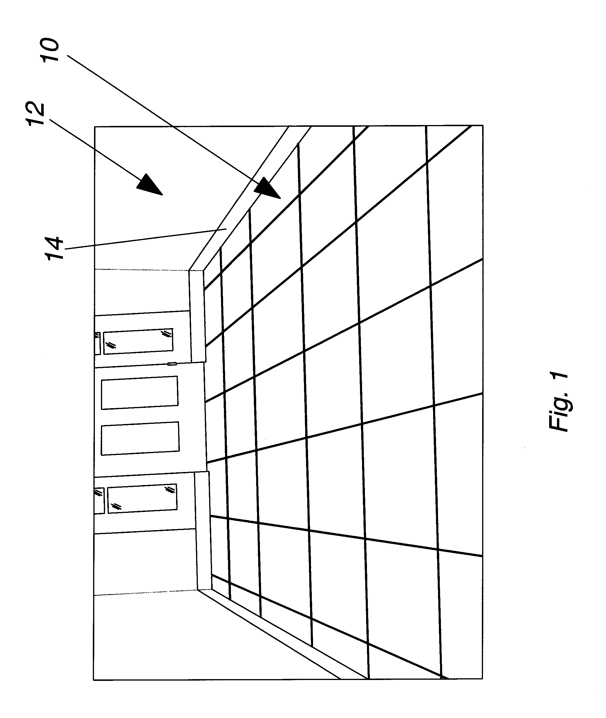
[0056]Referring to FIG. 1, an illustrative example of the functionally bonded system, referred to generally as 10, is shown. The functionally bonded system 10 is shown placed in an entry way 12 of a residential building and installed over an existing tile flooring system. Accordingly, the functionally bonded system 10 was installed without removal of the previously laid down tile. In addition, removal of the trim 14 around the perimeter of entry way 12 was not required as the installation of the functionally bonded system 10 was accomplished without a removal step.

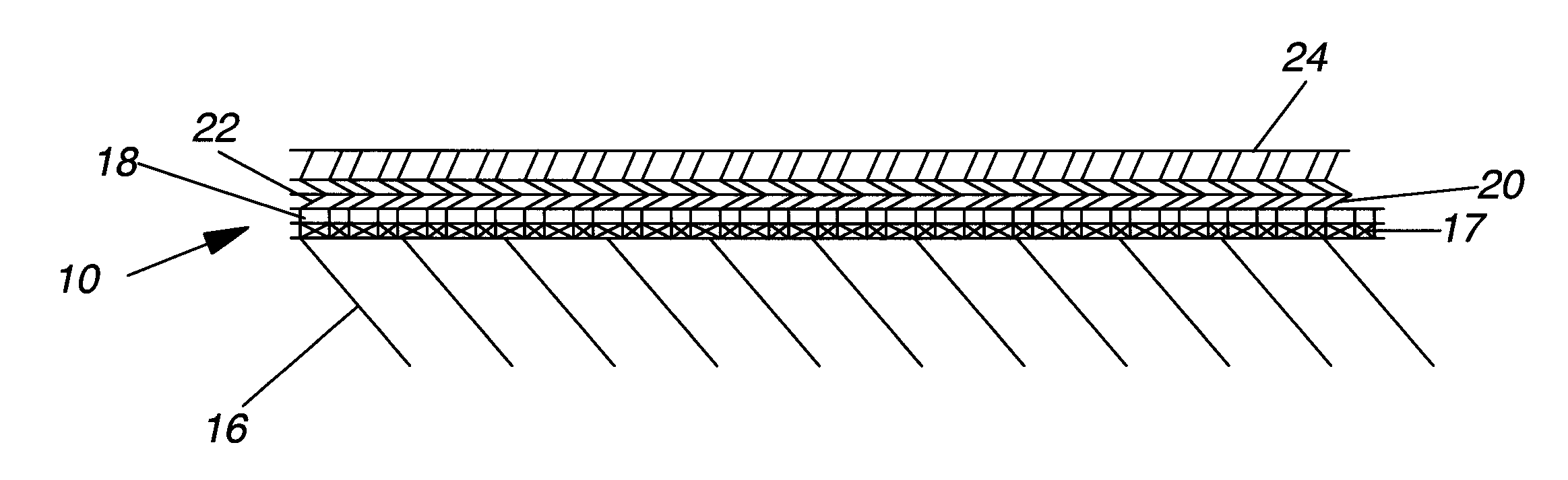
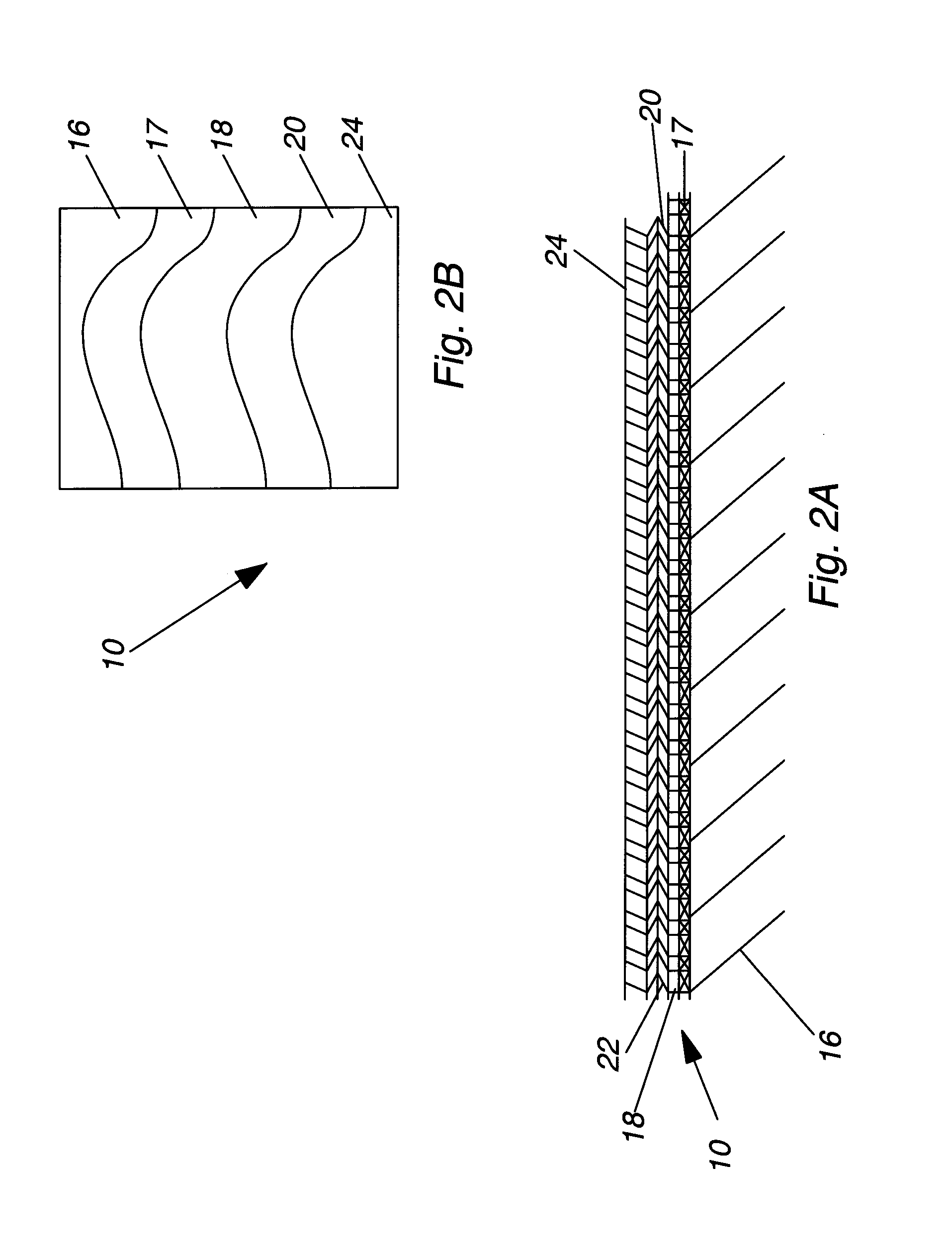
[0057]FIG. 2A is a diagramm...


PUM

PropertyMeasurementUnit
thicknessaaaaaaaaaa
thickaaaaaaaaaa
hydrophilicaaaaaaaaaa

Abstract

The present invention describes a decorative surface covering comprising a plurality of component layers, structural and/or chemical, chemically bonded to the surface, together forming a unique single unit, monolithic decorative surface overlay, referred to generally herein as a functionally bonded system. The functionally bonded system is designed to be flexible, expandable, and functional, providing the same durability as pre-existing flooring or horizontal surfaces. While the individual components have various properties, the chemical bonding of one layer to an adjacent layer above and/or below provides for a unique surface covering that is decorative and functional. The functionally bonded system can be installed, retrofitted and bonded to a raw concrete floor foundation, countertops and other horizontal surfaces or to such surfaces having an existing ceramic tile, porcelain tile, concrete, VCT (Vinyl), asbestos (VAT) composite tile, hardwood floor, laminate or engineered wood floor, other synthetic or natural materials, or glass or architectural glass.

Description

REFERENCE TO RELATED APPLICATIONS[0001]In accordance with 37 C.F.R 1.76, a claim of priority is included in an Application Data Sheet filed concurrently herewith. Accordingly, the present invention claims priority under 35 U.S.C. §119(e) to U.S. Provisional Application 61 / 643,709 entitled “DECORATIVE COMPOSITE FLOOR SURFACE OVERLAYMENT SYSTEM AND APPLICATION PROCESS WITH MONOLITHIC FINISH” filed on May 7, 2012; to U.S. Provisional Application 60 / 918,423, entitled “DECORATIVE COMPOSITE TILE FLOOR OVERLAYMENT APPLICATION PROCESS WITH MONOLITHIC FINISH” filed on Nov. 28, 2011; and to U.S. Provisional Application 60 / 185,139, entitled “DECORATIVE COMPOSITE TILE FLOOR OVERLAYMENT APPLICATION PROCESS WITH MONOLITHIC FINISH” filed on Sep. 28, 2011. The contents of each of the above referenced applications are herein incorporated by reference in its entirety.FIELD OF THE INVENTION[0002]The present invention relates to systems and methods useful for residential and business improvement projec...

Claims


Application Information

Patent Timeline
Patent Type & Authority Applications(United States)
IPC IPC(8): E04C2/26B32B37/12
CPCE04C2/26B32B37/12B29L2031/732B29C63/48B29C2063/485E04F15/12E04F15/163Y10T428/2481Y10T428/24851Y10T428/24926Y10T428/24802Y10T156/10
Inventor FERGUSON, SAMUELIRELAND, BRIAN
Owner FINDEX COM
Why Eureka
Try Eureka