
Fighting Arts Shield Like Device

a shield and shield technology, applied in the field of fighting arts, can solve the problem that no one provides this type of contact surface developmen

Inactive Publication Date: 2013-11-07
PARTLO LOREN GEORGE
View PDF11 Cites 27 Cited by
  • Summary
  • Abstract
  • Description
  • Claims
  • Application Information

AI Technical Summary

Benefits of technology

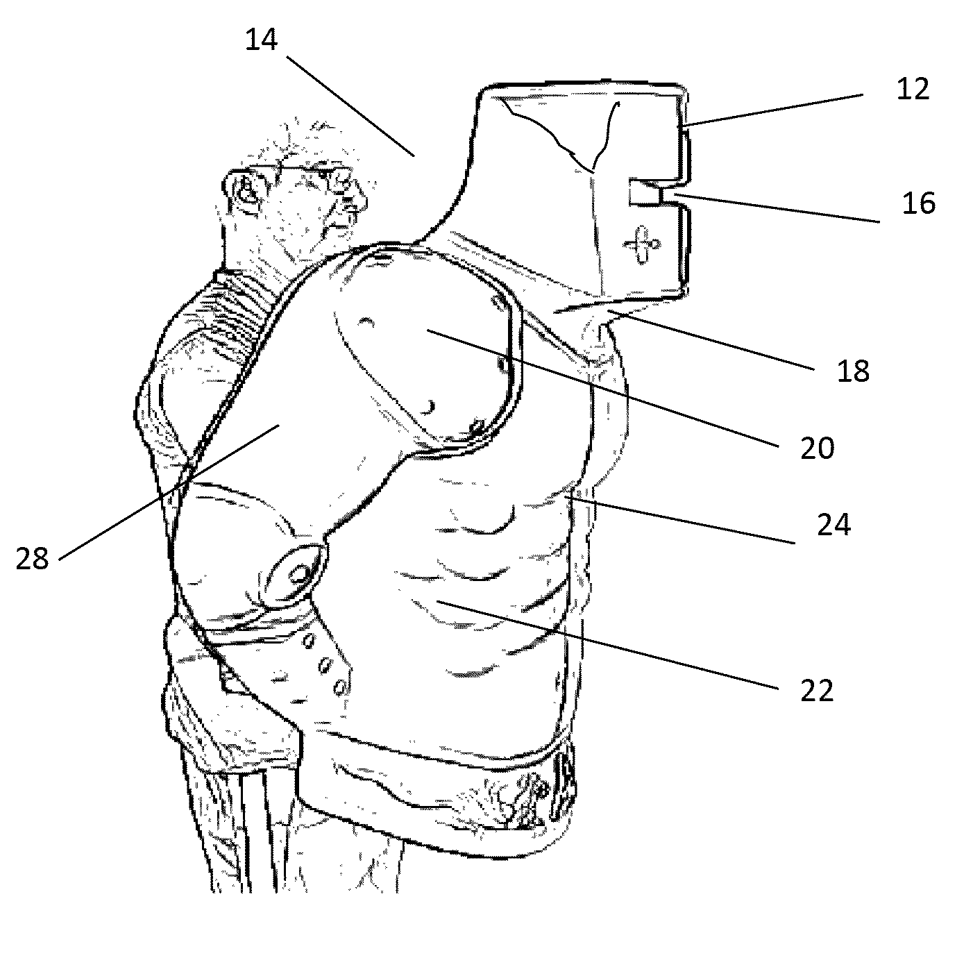
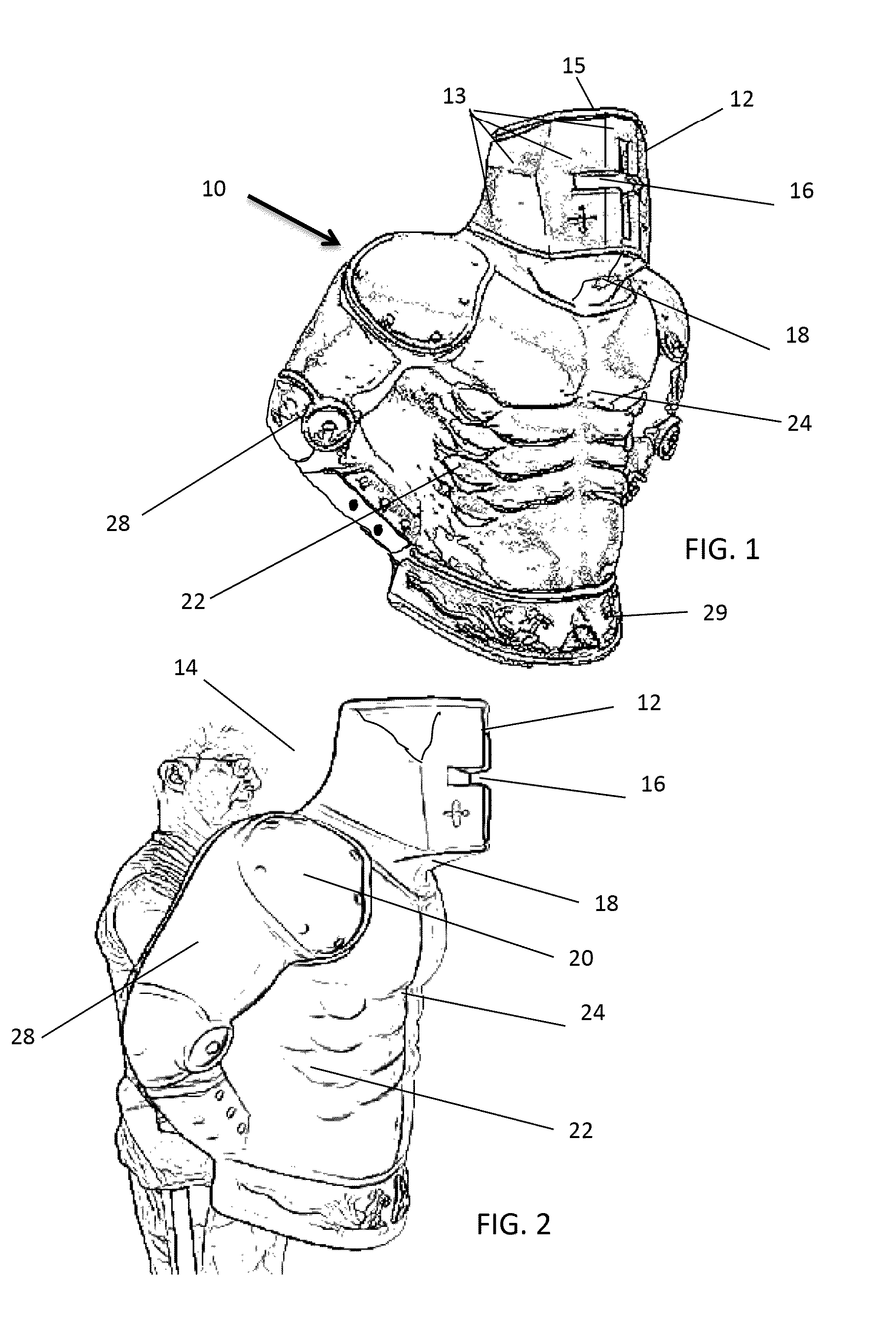
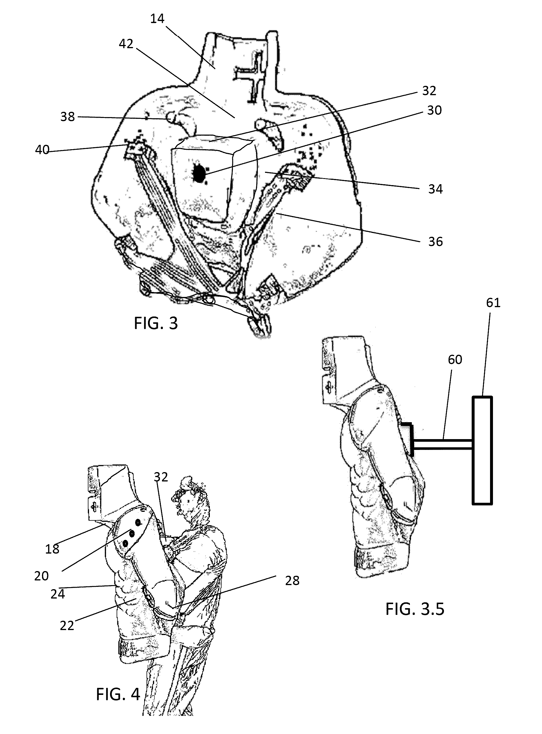
The shield like device has a head-like protrusion that has angular target areas designed to be met at a 90 degree angle. It is set forward of other striking areas to provide a safety space buffer and also has an offset forward of other striking areas to create an extended chin-like striking area. Additionally, the device is made of a hard non-force absorbent material with a foam filled portion between the front and back walls to increase rigidity and durability.

Problems solved by technology

Other inventions have striking areas but their terminology intent is to simply identify locations to be hit, none provide this type of contact surface development when defining the striking area.

Method used


Image

  • Fighting Arts Shield Like Device
  • Fighting Arts Shield Like Device
  • Fighting Arts Shield Like Device

Examples


second embodiment

[0150]FIG. 9 shows the invention created out of resilient force absorbent foam. The features of the shield like device provides safety for the holder and because the device is made totally of a resilient force absorbent foam; or a composition thereof that may or may not be sealed or covered to improve durability and cleanliness. The resilient force absorbent foam design construction would not require the user to wear protective equipment to engage the target with powerful strikes without being harmed by the shield like device. This design would be appealing for working with children.

[0151]FIG. 10a is a perspective front view and FIG. 10b is a perspective back view of the internal flexible plastic core structure that would be the internal structure within the third and ninth embodiments of the shield like device. The third embodiment is a resilient force absorption shield like device with a flexible plastic core component that provides additional firmness and support to the resilient...

fourth embodiment

[0152]FIG. 11 is a perspective view of the fourth embodiment depicting the shield like device that is created of a hard non-force absorbent material. This embodiment would be constructed of plastic, fiber-reinforced plastic or lightweight non-flexing metal. This type of shield like device is ideal for boxing coaches who desire their students to wear extra heavy gloves to improve muscle use and work on proper contact with the target or MMA practitioners who are working on developing toughness and strength in their attacking tools while working on striking.

fifth embodiment

[0153]FIG. 12 is a perspective front view of a fifth embodiment depicting the shield like device created of a hard non-force absorbent material with a foam filled portion between the front and back of the shield like device to increase the rigidity and durability of the device to be able to withstand heavy surface impacts. This embodiment would be an excellent choice for martial arts instructors or law enforcement personnel who want to use the shield like device for weapons training.


PUM


Abstract

A fighting arts shield like device designed to be carried or mounted. Through hitting the apparatus the contestant can condition and develop muscles and technique. The device may be either solid or hollow. The shield front is specifically developed to represent striking areas found on a human target and developed such that a properly delivered strike will land solidly; improper or techniques delivered from the wrong distance will not land appropriately. The backside is uniquely developed with features that enhance the holder's ability to hold and direct the shield thereby enhancing its utility. The shield is carried in a boxing on-guard position. The shield like device may have an optional electrical component that allows measurements to be made of the speed, power and force vectors of strikes where data may be instantaneously presented by audio and visual indicators or disaggregated or used at a later date.

Description

CROSS-REFERENCE TO RELATED APPLICATIONS[0001]U.S. Patent Documents2,574,046November 1951Logan2,994,534August 1961Davis et al.3,759,515September 1973Crooks3,896,497July 1975Rhee4,478,408October 1984Bruckner4,546,966October 1985Segura4,889,334December 1986Pardo4,974,833December 1990Hartman et al.4,991,231February 1991Swift5,009,414April 1991Bass5,209,691May 1993Ekstein5,232,368August 1993Morgia5,254,062October 1993Hoffman5,277,679January 1994Wells5,281,191January 1994DeSousa5,362,289November 1994Holt5,458,552October 1995Mara5,542,667August 1996Lezdey et al.5,501,649March 1996Queppet5,582,561December 1996Gonzalez5,605,336February 1997Gaoiran et al.5,723,786March 1998Klapman5,741,970April 1998Rubin6,258,013July 2001Dabney6,925,851August 2005Reinbold et al.0,216,228November 2003Rast0,258,515November 2006Kang et al.7,308,818B2December 2007Considine et al.7,909,749March 2011Sheedy8,011,222September 2011Wilber8,029,422B2October 2011Stong et al.Primary Examiner:Assistant Examiner:Attorney, A...

Claims


Application Information

Patent Timeline
IPC IPC(8): A63B69/32A63B69/34
CPCA63B69/26A63B71/0622A63B2071/0063A63B2071/0625A63B2071/065A63B2071/0658A63B2208/12A63B2220/30A63B2220/62A63B2220/801A63B2220/806A63B2225/15A63B2225/50A63B2230/04A63B2230/75A63B2244/102A63B2244/106A63B2225/74A63B2244/10A63B69/28A63B69/215A63B69/32
Inventor PARTLO, LOREN GEORGE
Owner PARTLO LOREN GEORGE
Learn More