Magnetic refrigeration system and vehicle air conditioning device

a refrigeration system and magnetic refrigeration technology, applied in the direction of machine operation, transportation and packaging, light and heating equipment, etc., can solve the problems of reduced cop (coefficient of performance) of magnetic refrigeration system, limited application of magnetic refrigeration system to special uses, and difficult application of magnetic refrigeration system to general-purpose products such as vehicle air conditioning devices

Inactive Publication Date: 2013-11-14
DENSO CORP
View PDF3 Cites 67 Cited by
  • Summary
  • Abstract
  • Description
  • Claims
  • Application Information

AI Technical Summary

Benefits of technology

[0018]In this way, the refrigerant whose temperature is increased by the hot heat generated in the magnetic working material can be made to flow directly into the first heat exchanger and the refrigerant whose temperature is decreased by the cold heat generated in the magnetic working material can be made to flow directly into the second heat exchanger. Hence, a heat exchange loss can be reduced when the hot heat and the cold heat generated in the magnetic working material are transported, and hence the COP of the magnetic refrigeration system can be improved.
[0039]Specifically, when the first heat exchanger is arranged downstream of the second heat exchanger in a flow of the blown air in the case, the first heat exchanger can heat the blown air, which is cooled and dehumidified by the second heat exchanger, thereby dehumidify the blown air at the time of heating the interior of the passenger compartment.

Problems solved by technology

By the way, in the magnetic refrigeration system of the patent document 1, the strong magnetic field generating device is constructed of a superconducting coil or the like so as to increase a temperature change in the magnetic working material and the application of the magnetic refrigeration system is limited to special uses.
Hence, it is difficult to apply the magnetic refrigeration system to a general-purpose product such as a vehicle air conditioning device.
However, in this case, there is presented an issue that the COP (Coefficient Of Performance) of refrigeration of the magnetic refrigeration system is reduced.
At this time, a heat exchange loss is increased between the magnetic working material and the heating medium.

Method used


Image

  • Magnetic refrigeration system and vehicle air conditioning device
  • Magnetic refrigeration system and vehicle air conditioning device
  • Magnetic refrigeration system and vehicle air conditioning device

Examples


first embodiment

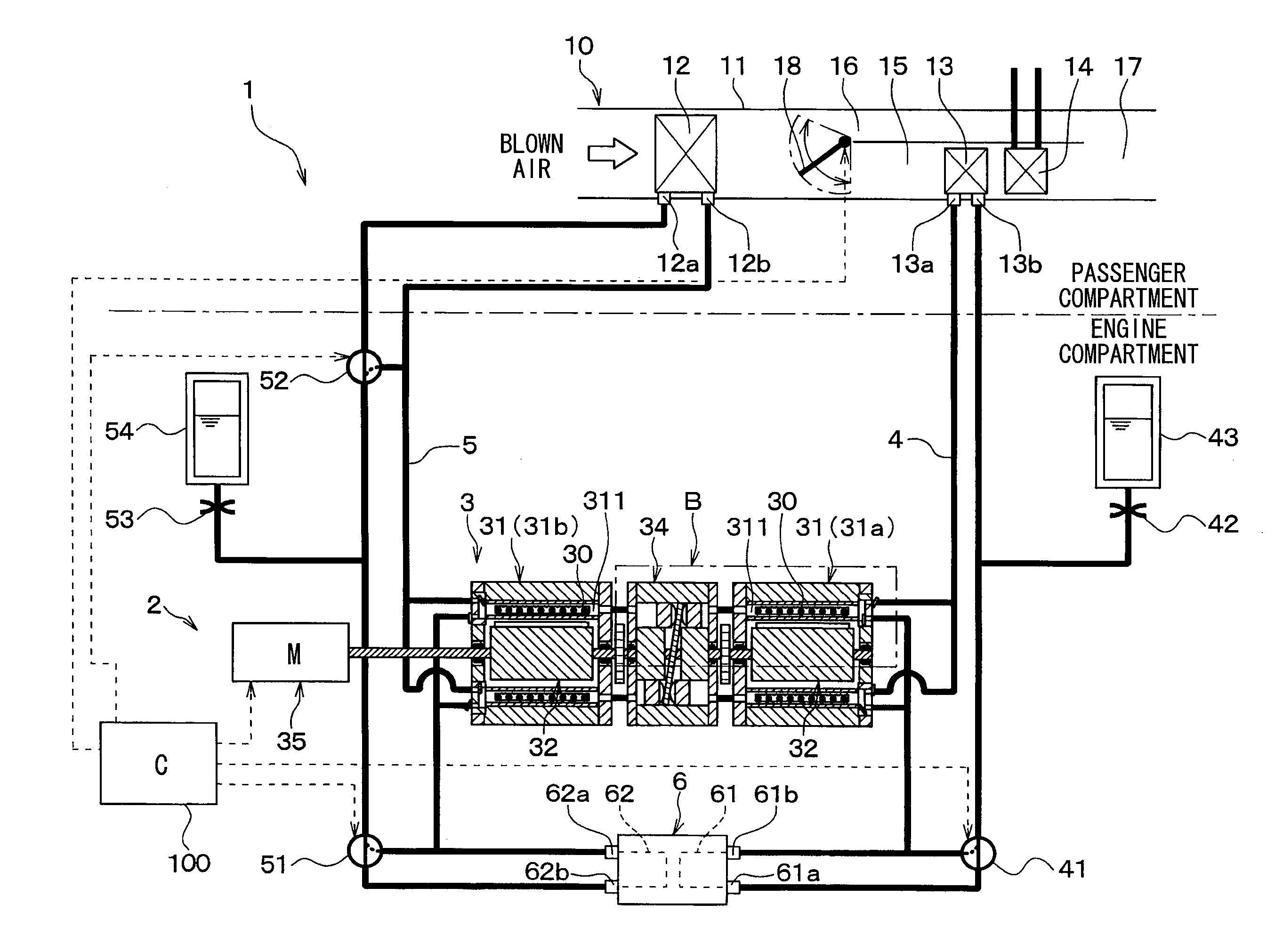
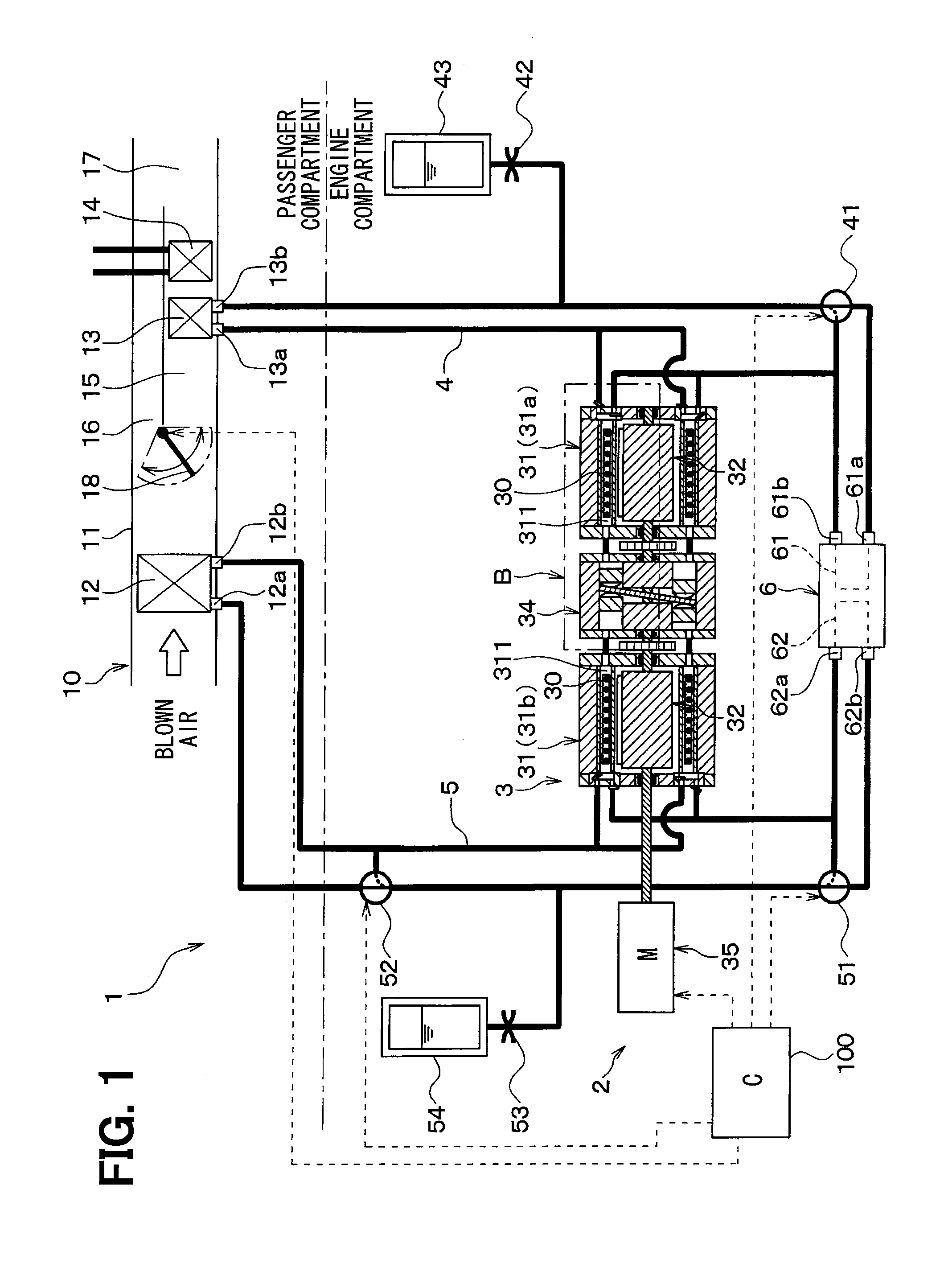
[0066]A first embodiment of the present disclosure will be described on the basis of FIG. 1 to FIG. 7. FIG. 1 is a general construction diagram of a vehicle air conditioning device 1 of the present embodiment. In the present embodiment, a magnetic refrigeration system 2 of the present disclosure is applied to the vehicle air conditioning device 1 for air-conditioning an interior of a passenger compartment of an automobile.

[0067]The vehicle air conditioning device 1 of the present embodiment is an air conditioning device mounted in the automobile acquiring a drive force for driving from an internal combustion engine (engine).

[0068]The vehicle air conditioning device 1, as shown in FIG. 1, is provided with the magnetic refrigeration system 2 arranged in an engine compartment, an indoor air conditioning unit 10 arranged in the passenger compartment, and an air conditioning control device 100.

[0069]The magnetic refrigeration system 2 of the present embodiment is constructed in such a wa...

second embodiment

[0184]Next, a second embodiment of the present disclosure will be described on the basis of FIG. 8. FIG. 8 is a general construction diagram of a vehicle air conditioning device 1 of the present embodiment. In the present embodiment, the descriptions of parts identical or equivalent to the parts in the first embodiment will be omitted or simplified.

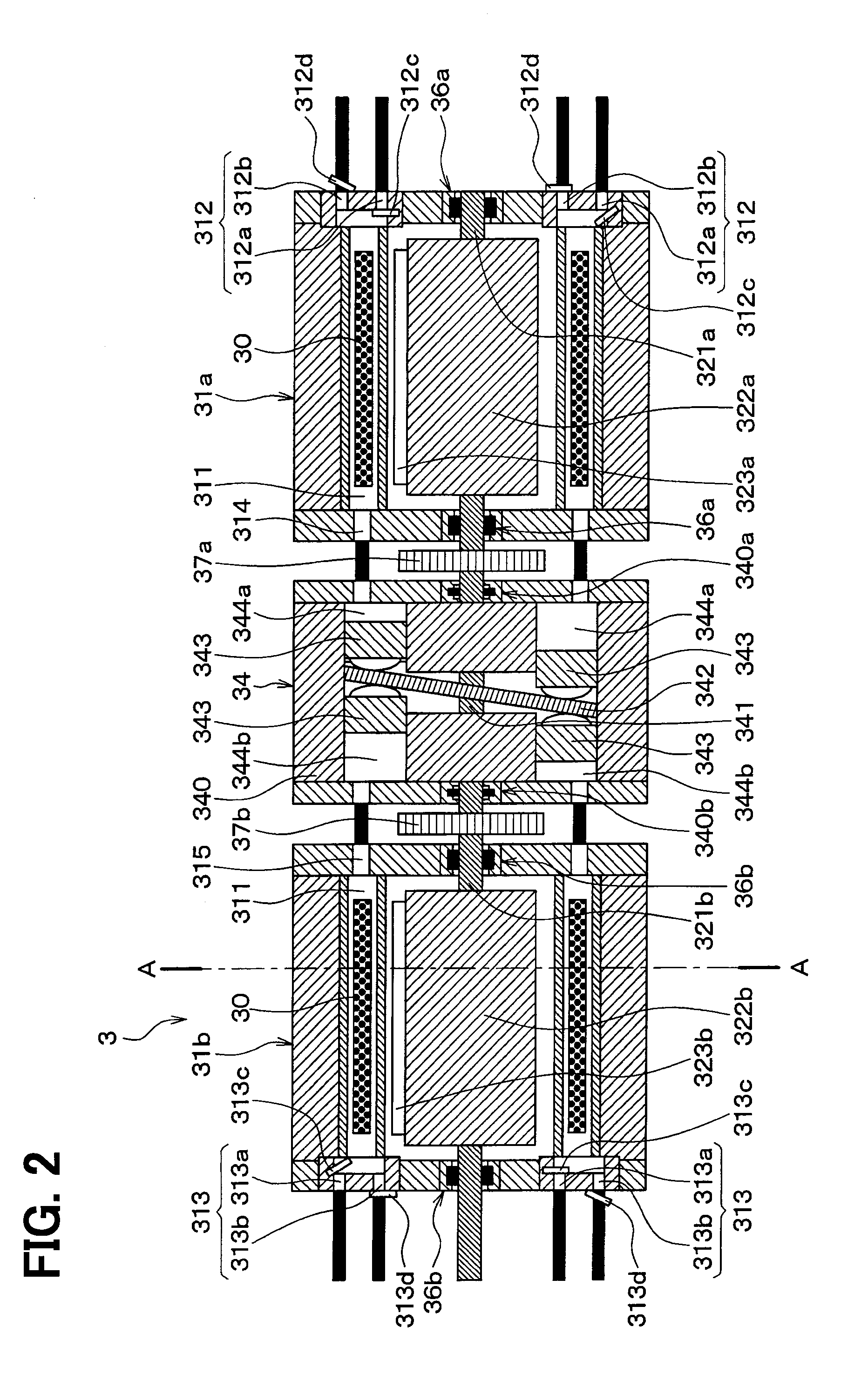
[0185]The first embodiment described above employs the following construction: that is, the refrigerant suction part 312a, 313a of the container 31a, 31b is provided with the suction valve 312c, 313c; and the refrigerant discharge part 312b, 313b of the container 31a, 31b is provided with the discharge valve 312d, 313d, whereby in each of the refrigerant circuits 4, 5, the refrigerant flows in one direction in order of the refrigerant ports 312, 313 of the container 31a, 31b, the refrigerant flow-in port 12a, 13a of the heat exchanger 12, 13, the refrigerant flow-out port 12b, 13b of the heat exchanger 12, 13, and the refrigerant ports 31...

third embodiment

[0192]Next, a third embodiment of the present disclosure will be described on the basis of FIG. 9. FIG. 9 is a general construction diagram of a vehicle air conditioning device 1 of the present embodiment. In the present embodiment, the descriptions of parts identical or equivalent to the parts in the first and the second embodiments will be omitted or simplified.

[0193]The second embodiment described above employs a construction in which the high temperature side refrigerant circuit 4 is provided with the first and the second check valves 44, 45 and in which the low temperature side refrigerant circuit 5 is provided with the third and the fourth check valves 56, 57. In contrast to this, the present embodiment employs a construction in which the refrigerant circuit 4 is provided with opening and closing valves 46, 47 and the refrigerant circuit 5 is provided with opening and closing valves 58, 59, the opening and closing valves being opened or closed according to a control signal fro...


PUM


Abstract

A magnetic refrigeration system constructed in such a way that a refrigerant transfer part transfers refrigerant from a first refrigerant discharge part of one refrigerant port to a first refrigerant circulation circuit after a magnetic field is applied to a magnetic working material by a magnetic field applying and removing part and that the refrigerant transfer part transfers refrigerant from a second refrigerant discharge part of other refrigerant port to a second refrigerant circulation circuit after the magnetic field is removed from the magnetic working material by the magnetic field applying and removing part.

Description

CROSS-REFERENCE TO RELATED APPLICATIONS[0001]The present disclosure is based on Japanese Patent Application No. 2011-14914 filed on Jan. 27, 2011, Japanese Patent Application No. 2011-110206 filed on May 17, 2011, and Japanese Patent Application No. 2011-281288 filed on Dec. 22, 2011, and the contents of those are incorporated herein by reference in their entirety.TECHNICAL FIELD[0002]The present disclosure relates to a magnetic refrigeration system and a vehicle air conditioning device to which the magnetic refrigeration system is applied.BACKGROUND ART[0003]There is proposed a magnetic refrigeration system utilizing a phenomenon (magnetocaloric effect) such that when a magnetic field is applied to a magnetic working material such as a magnetic material, the magnetic working material generates heat and such that when the magnetic field is removed from the magnetic working material, the magnetic working material is decreased in temperature (see, for example, patent document 1).[0004...

Claims


Application Information

Patent Timeline
Patent Type & Authority Applications(United States)
IPC IPC(8): F25B21/00
CPCF25B21/00B60H1/32F25B2321/0022Y02B30/00B60H1/00864B60H1/00885F25B2321/002
Inventor MORIMOTO, TSUYOSHIWATANABE, NAOKIYATSUZUKA, SHINICHINISHIZAWA, KATZUTOSHI
Owner DENSO CORP
Why Eureka
Try Eureka