Heat exchanger

a heat exchanger and composite technology, applied in indirect heat exchangers, lightening and heating apparatus, transportation and packaging, etc., can solve the problems of reducing the length of the refrigerant tubes that form the condenser, reducing the heat exchange rate of the refrigerant radiator as a whole, and reducing the heat exchange rate of the subcooling portion of the refrigerant radiator

Inactive Publication Date: 2015-10-15
DENSO CORP
View PDF11 Cites 17 Cited by
  • Summary
  • Abstract
  • Description
  • Claims
  • Application Information

AI Technical Summary

Benefits of technology

[0008]However, the subcooling portion in the refrigerant radiator has an extremely low heat transmitting rate on tube wall surfaces in comparison with a condenser (the heat radiating portion in the refrigerant radiator other than the subcooling portion). In contrast, the refrigerant tubes that form the condenser have a high heat transmitting rate on the tube wall surfaces, and have a high heat exchanging performance. Therefore, when the length of the tubes that form the subcooling portion is increased, the length of the refrigerant tubes that form the condenser is reduced, so that the heat exchanging performance of the refrigerant radiator as a whole may be deteriorated.
[0012]Therefore, lengths of the most downstream first tubes does not have to be increased in order to achieve a desired temperature as the temperature of the first fluid on the outlet side of the heat exchanger, that is, lengths of first tubes which do not form the final path does not have to be decreased, and hence reduction of the heat exchanging performance as the entire heat exchanger may be limited.

Problems solved by technology

However, the subcooling portion in the refrigerant radiator has an extremely low heat transmitting rate on tube wall surfaces in comparison with a condenser (the heat radiating portion in the refrigerant radiator other than the subcooling portion).
Therefore, when the length of the tubes that form the subcooling portion is increased, the length of the refrigerant tubes that form the condenser is reduced, so that the heat exchanging performance of the refrigerant radiator as a whole may be deteriorated.

Method used


Image

  • Heat exchanger
  • Heat exchanger
  • Heat exchanger

Examples


first embodiment

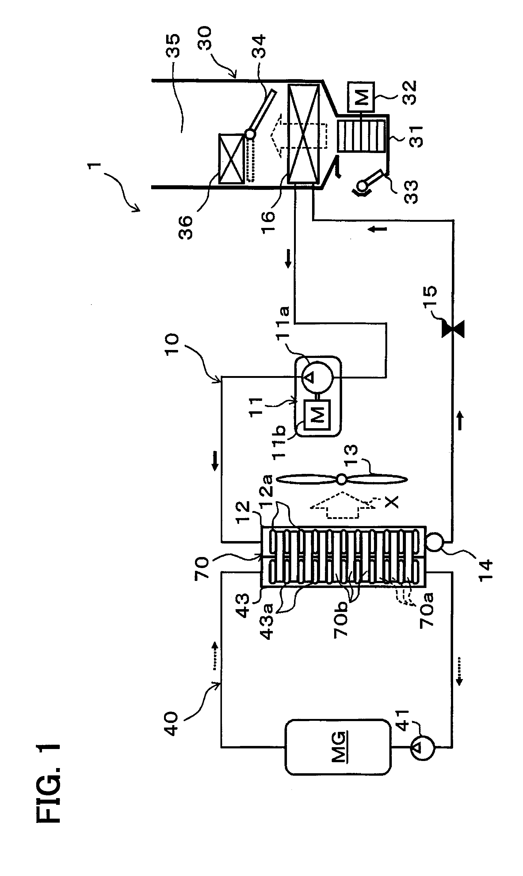
[0032]A first embodiment of the present disclosure will be described with reference to FIG. 1 to FIG. 7. In the present embodiment, a heat exchange system of the present disclosure is applied to a vehicle air conditioning apparatus 1 for so-called a hybrid vehicle that obtains a drive force for traveling a vehicle from an internal combustion engine (an engine) and a traveling electric motor MG.

[0033]The hybrid vehicle is capable of being switched between a traveling state in which the engine is activated or stopped depending on a traveling load of the vehicle and a drive force is obtained both from the engine and the traveling electric motor MG to travel and a traveling state in which the engine is stopped and the drive force is obtained only from the traveling electric motor MG to travel. Accordingly, in the hybrid vehicle, a vehicle fuel efficiency for normal vehicles which obtain the drive force for traveling the vehicle only from the engine can be improved.

[0034]The heat exchang...

second embodiment

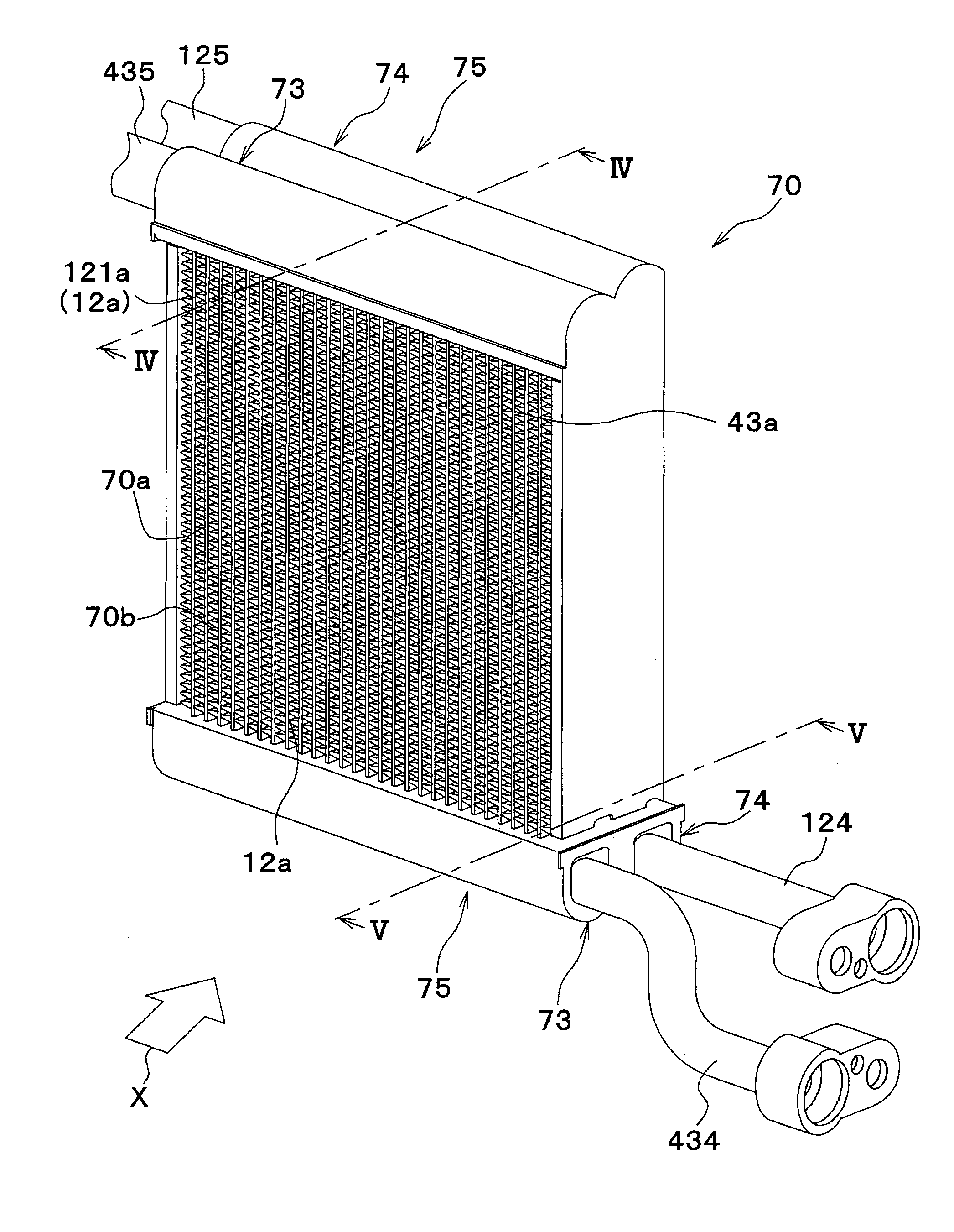
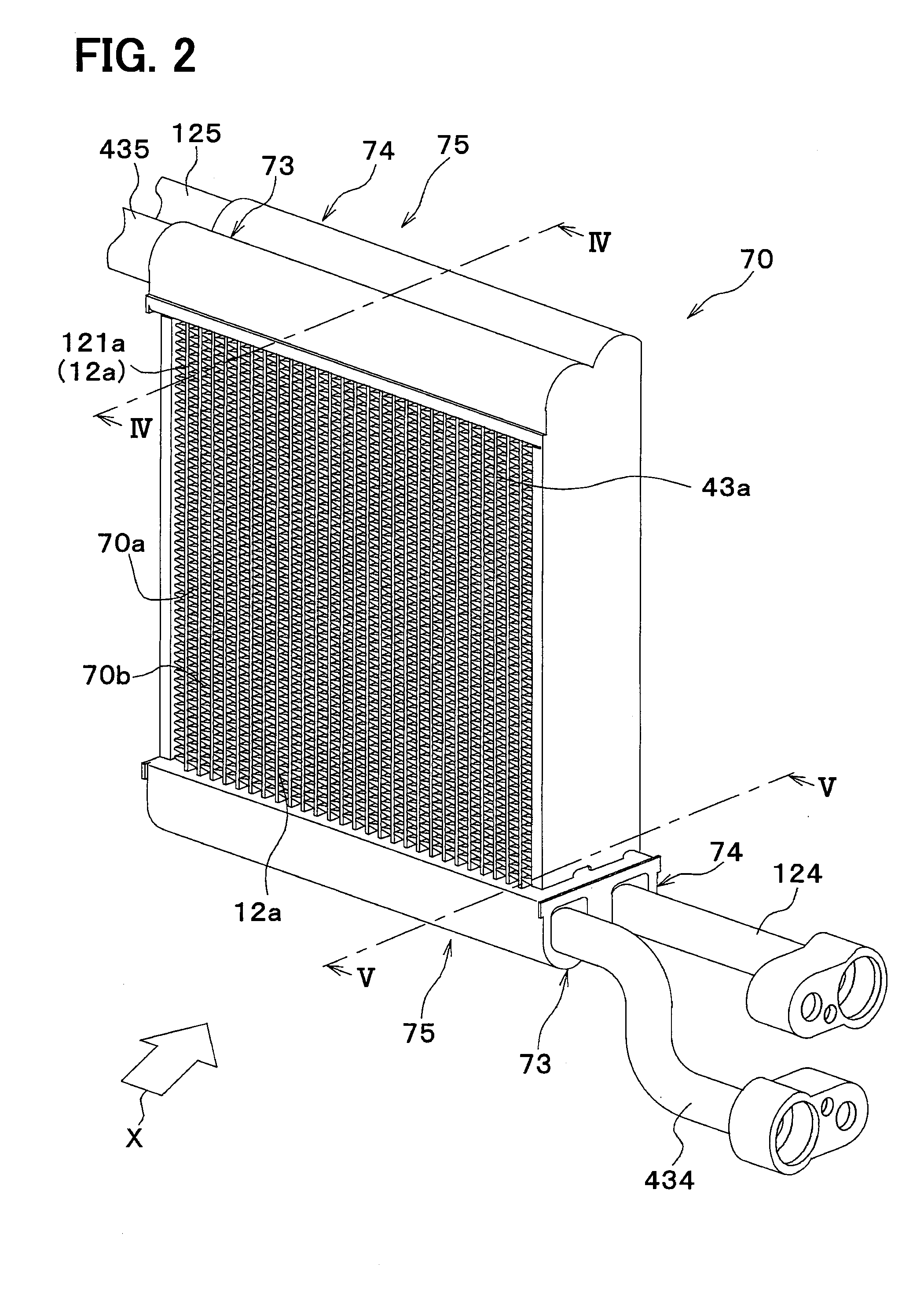
[0142]Subsequently, a second embodiment of the present disclosure will be described with reference to FIG. 8. In comparison with the first embodiment described above, the second embodiment is different in a point that a first core portion 701 includes also a coolant tube 43a. In FIG. 8, refrigerant tubes 12a are illustrated with diagonal hatching and the coolant tube 43a is illustrated by dot hatching for clarifying the drawing.

[0143]As illustrated in FIG. 8, the first core portion 701 of a composite-type heat exchanger 70 of the present embodiment is provided with the coolant tube 43a. In the present embodiment, although the number of the refrigerant tubes 12a (nine in this example) is larger than the number of the coolant tube 43a (one in this example) in the first core portion 701. Surfaces of outer fins 70b are provided with a plurality of shutter-like louvers 700 formed along the flowing direction of the outside air by cutting and rising.

[0144]In the outer fin 70b between the m...

third embodiment

[0149]Subsequently, a third embodiment of the present disclosure will be described with reference to FIG. 9. The third embodiment is different in the flow of the refrigerant of the first core portion 701 in comparison with the first embodiment.

[0150]As illustrated in FIG. 9, an upstream side partitioning member 732a configured to partition the upstream side coolant space 731 in the internal space of the second upstream side tank unit 730b into two parts in the longitudinal direction is arranged in the second upstream side tank unit 730b. A space closer to the first core portion 701 (the left side on the paper plane) out of the two internal spaces of the tank partitioned by the upstream side partitioning member 732a (hereinafter, referred to as an upstream side refrigerant space 731a) communicates with the most downstream refrigerant tubes 121a, but not communicate with coolant tube 43a. A refrigerant outflow pipe 125 is connected to the upstream side refrigerant space 731a.

[0151]In...


PUM


Abstract

In a composite-type heat exchanger capable of exchanging heat among three types of fluids, an outside air passage is provided in a periphery of refrigerant tubes and coolant tubes, and the outside air passage includes outer fins that promote heat exchange among a refrigerant, an outside air and a coolant. The outer fins include refrigerant side heat connecting portions configured to thermally connect the refrigerant tubes, and coolant side heat connecting portions configured to thermally connect the refrigerant tubes and the coolant tubes. In a first core portion including most downstream refrigerant tubes which constitute a final path, which is the most downstream side path in a direction of the refrigerant flow, the refrigerant side heat connecting portions is larger in number than the coolant side heat connecting portions.

Description

CROSS REFERENCE TO RELATED APPLICATION[0001]This application is based on and incorporates herein by reference Japanese Patent Application No. 2012-249441 filed on Nov. 13, 2012.TECHNICAL FIELD[0002]The present disclosure relates to a composite-type heat exchanger configured to be capable of performing heat exchanges among three kinds of fluids.BACKGROUND ART[0003]Conventionally, a composite-type heat exchanger configured to be capable of performing heat exchanges among three types of fluids is known. For example, disclosed in Patent Document 1 is a composite-type heat exchanger including a refrigerant radiator that performs heat exchange between a refrigerant (a first fluid) discharged from a compressor in a refrigeration cycle and a blown air (a third fluid) such that a heat of the discharged refrigerant is radiated to the blown air, and a radiator that performs heat exchange between a coolant (a second fluid) for cooling an engine and a blown air to radiate heat of the coolant to ...

Claims


Application Information

Patent Timeline
Patent Type & Authority Applications(United States)
IPC IPC(8): F28F9/02
CPCF28F9/0246F25B39/04F28F27/02B60H1/00328B60H1/00335F28F9/0224F28F9/0278F28D1/0426F28D1/05391F28F2270/00F28F2215/02F28F2009/004F28F9/0251F28F9/001
Inventor KATOH, YOSHIKISAITO, MITSUYOSHI
Owner DENSO CORP
Why Eureka
Try Eureka