
Vibration isolator

a technology of vibration isolation and isolator, which is applied in the direction of non-rotating vibration suppression, vibration suppression adjustment, magnetic spring, etc., can solve the problems of high cost, high cost, and special constraints on the design of vibration isolation, and achieve low stiffness and perform well over a wider range of movemen

Active Publication Date: 2013-11-14
ASML NETHERLANDS BV
View PDF10 Cites 10 Cited by
  • Summary
  • Abstract
  • Description
  • Claims
  • Application Information

AI Technical Summary

Benefits of technology

The vibration isolator uses a magnetic spring that uses a vertical air gap instead of a horizontal one, which results in a higher magnetic force with low stiffness. This allows for individual magnets to attract or retract each other, resulting in a net magnetic force that pushes the load structure upward, against gravity. The use of permanent magnets makes the system effective against vibrations and other mechanical disturbances. If there are no displacement movements, the system can automatically bring the load structure back to its original position. Additionally, the system can use compensating units to stabilize the load structure and improve its stability.

Problems solved by technology

Vibrations and other types of mechanical disturbances in such machines easily show up as a major factor in limiting the achievable accuracy, hence require significant reduction.
Such demands impose special constraints on a vibration isolation design.
Since, in many cases, the structural design of the isolated mass provides little inherent vibration isolation, and passive means provide insufficient isolation over the full required bandwidth, active means are often utilized to provide vibration control.
The isolation bandwidth of the currently often used pneumatic isolators is generally limited.
As a result the vibrations at elevated frequencies are not properly extinguished, which limits the performance of the machine being isolated.
Furthermore, air bearings are only suitable for vacuum conditions if significant structural changes are applied which may adversely affect their performance.
It is, however, a disadvantage of this magnetic spring type that the low spring stiffness is very local and as a result the spring stiffness varies significantly with the position.
Furthermore, such a double-sided topology requires a ‘sandwiched’ construction which may proof to be disadvantageous if the vertical spring force exerted by such magnetic spring has to be led around the spring by mechanical means.

Method used


Image

  • Vibration isolator
  • Vibration isolator
  • Vibration isolator

Examples


Embodiment Construction

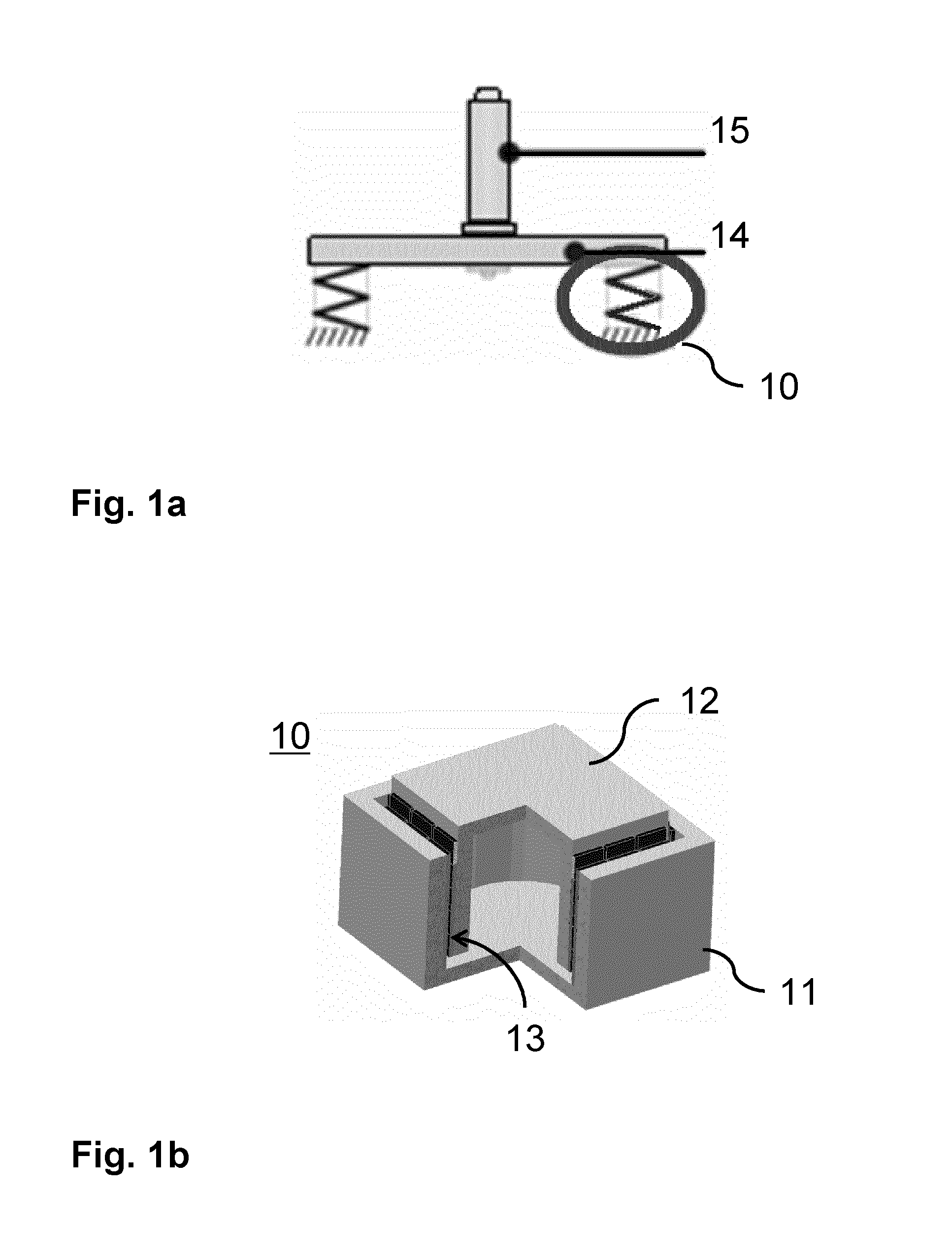
[0029]FIG. 1a shows a platform 14 supported by vibration isolators 10 according to the invention. The platform 14 carries a payload 15 which requires very accurate positioning and vibration isolation. In many technical areas like, e.g., lithographic industry, electron beam microscopy and space applications, it is very important to reduce the influence of vibrations on the accuracy of the positioning systems. The exemplary platform 14 is used in a lithographic machine and carries a lens system 15 for accurately focusing a laser bundle on a silicon wafer positioned underneath the platform 14. Vibration isolators 10 reduce the vibrations in this part of the machine and keep the lens system 15 aligned with the wafer.

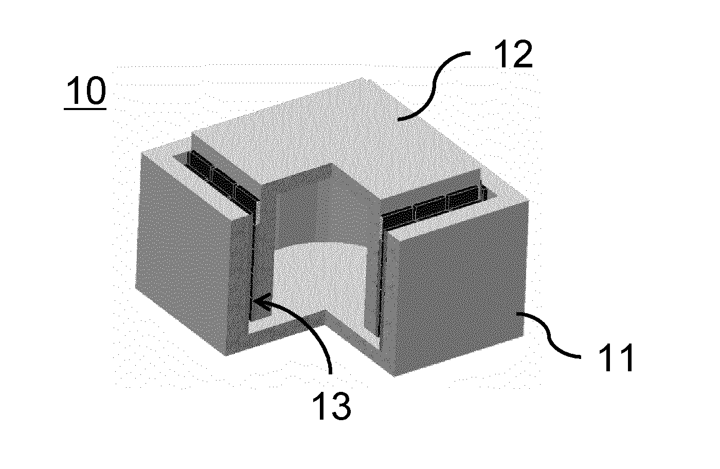
[0030]FIG. 1b shows a close-up of a vibration isolator 10 according to the invention. The vibration isolator comprises a base structure 11 and a load structure 12. The load structure 12 fits into a receiving volume of the base structure 11, such that vertical airgaps 13 are ...


PUM


Abstract

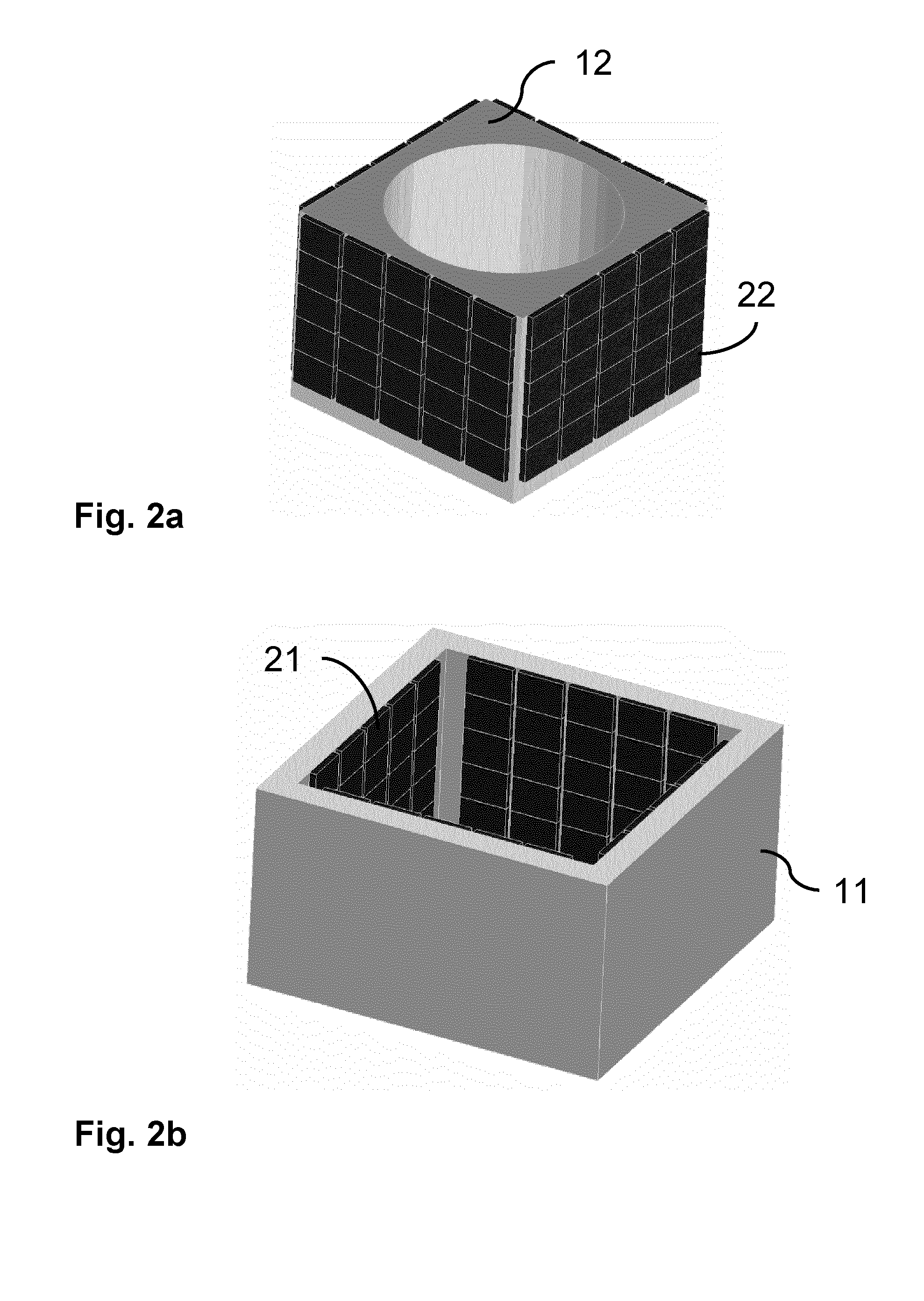
A vibration isolator is provided comprising a base structure, a load structure and at least one vertical air gap formed by opposing and substantially parallel walls of the base structure and the load structure. The opposing walls being at least partly covered by respective arrays of permanent magnets, neighboring magnets in the arrays having alternating magnetization directions, an arrangement of the permanent magnets in the arrays being such that a gravitational force on the load structure is substantially compensated by a net magnetic force of the base structure on the load structure.

Description

FIELD OF THE INVENTION[0001]This invention relates to a vibration isolator comprising a base structure, a load structure and means for compensating a gravitational force on the load structure.BACKGROUND OF THE INVENTION[0002]Many industrial engineers, such as in lithographic industry, electron beam microscopy and space applications, deal with accurate positioning systems. Vibrations and other types of mechanical disturbances in such machines easily show up as a major factor in limiting the achievable accuracy, hence require significant reduction. Precise reproduction of the features that continue to get smaller requires good isolation from the environment while productivity concerns driven by market requirements require faster motion. Such demands impose special constraints on a vibration isolation design. Since, in many cases, the structural design of the isolated mass provides little inherent vibration isolation, and passive means provide insufficient isolation over the full requi...

Claims


Application Information

Patent Timeline
IPC IPC(8): F16F6/00
CPCF16F6/005F16F15/03F16F6/00
Inventor JANSSEN, JEROEN LODEVICUS GERARDUSPAULIDES, JOHANNES JACOBUS HUBERTUSLOMONOVA, ELENA ANDREEVNA
Owner ASML NETHERLANDS BV
Learn More