
Hub-bearing assembly for a vehicle wheel

a technology for vehicle wheels and hubs, applied in the direction of mechanical equipment, rigid support of bearing units, transportation and packaging, etc., can solve the problems of oxidation and corrosion, risk of damage, galvanic corrosion, etc., and achieve the effect of simple, low cost and efficient application

Inactive Publication Date: 2013-11-14
AB SKF
View PDF7 Cites 5 Cited by
  • Summary
  • Abstract
  • Description
  • Claims
  • Application Information

AI Technical Summary

Benefits of technology

The invention aims to protect cylindrical surfaces in a simple, low-cost, and efficient way, overcoming the drawbacks of existing methods. Another goal is to provide a protective covering that can be applied quickly.

Problems solved by technology

When two metal parts come into contact with each other, the presence of moisture and / or oxygen in the air is frequently the cause of oxidation and corrosion, for example galvanic corrosion, which occurs both at the interface of the surface of the hub for centring the wheel and at the interface of the surface of the outer ring and the corresponding opening in the upright where the outer ring of the bearing is fixed.
In such cases, the two metal parts making contact (wheel and bearing on the axially outer (outboard) side or bearing and upright on the axially inner (inboard) side) tend to adhere firmly and risk being damaged when they are separated with force from each other during maintenance operations.
The application of paints is time-consuming and therefore is not compatible with production processes which require high speeds, in particular if drying or solidification of the paint takes place by exposure to air.
If the solidification process is accelerated by using ultraviolet light, costly investment is required.
Coated metal sleeves are particularly costly.

Method used


Image

  • Hub-bearing assembly for a vehicle wheel
  • Hub-bearing assembly for a vehicle wheel
  • Hub-bearing assembly for a vehicle wheel

Examples


Embodiment Construction

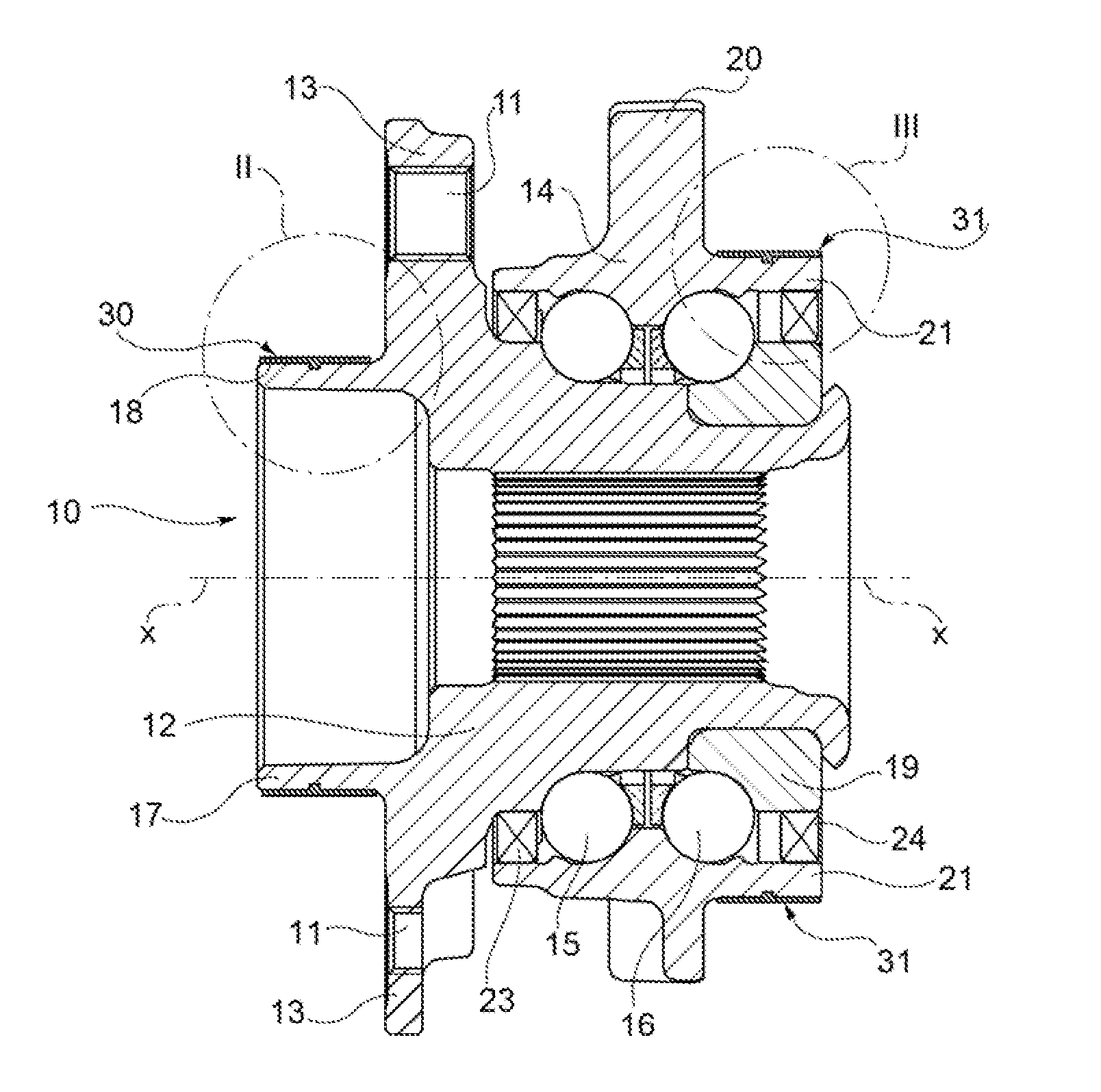
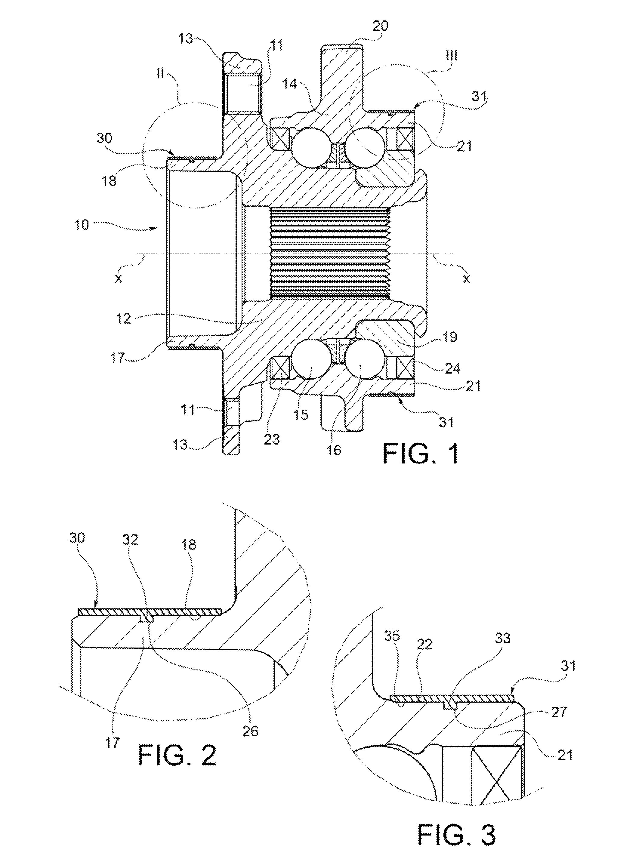
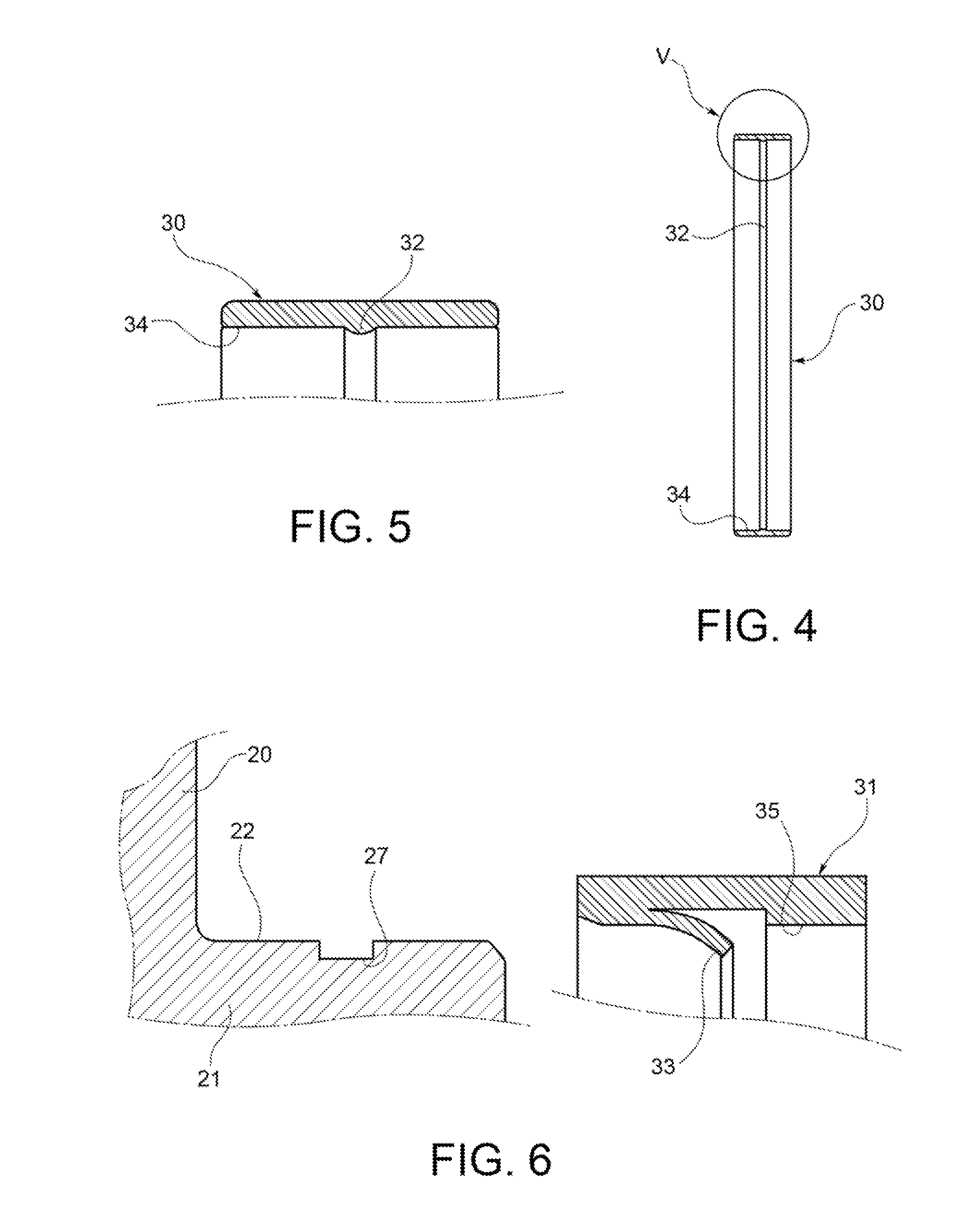
[0017]With reference initially to FIG. 1, a hub-bearing assembly is shown overall by 10. The assembly 10 is used to mount rotatably a wheel (not shown) on an upright (not shown) of the vehicle suspension, about a central axis of rotation x. Throughout the present description and in the claims, terms and expressions indicating positions and directions, such as “radial” and “axial”, are to be understood as referring to the axis of rotation x of the hub-bearing assembly. Expressions such as “axially inner” and “axially outer” are instead understood as referring to the condition mounted on the vehicle.

[0018]The hub-bearing assembly 10 includes a flanged hub 12 rotatable about the axis x, a flange 13 integral with the flanged hub 12 and transverse to the axis x, a stationary ring 14 arranged radially on the outside of the hub 12, and two ring arrangements 15, 16 of rolling members, in this case bearing balls, arranged between the outer stationary ring and the flanged hub. The invention i...


PUM


Abstract

A hub-bearing assembly for a vehicle wheel, the assembly being provided with at least one annular metal element having an axial tubular appendage adapted for being fitted into a central bore of a wheel or a bore of a suspension upright of the vehicle, wherein the tubular appendage has a cylindrical outer surface with an annular groove; the assembly also being provided with a sleeve of plastic material, which is mounted on the tubular appendage so as to cover the outer cylindrical surface and has an inner cylindrical surface with a radially inwardly protruding relief which snap-engages in the annular groove so as to axially lock the sleeve on the tubular appendage.

Description

CROSS-REFERENCE TO RELATED APPLICATION[0001]This application is a United States Non-Provisional Utility Patent Application claiming the benefit of Italian Patent Application Number TO2012A000360 filed on Apr. 23, 2012, which is incorporated herein in its entirety.TECHNICAL FIELD OF THE INVENTION[0002]The present invention relates to a hub-bearing assembly for a vehicle wheel.BACKGROUND OF THE INVENTION[0003]Hub-bearing assemblies for the wheel of a motor-vehicle are known, in which assemblies a hub forms a tubular appendage projecting from the axially outer side of the hub and having an outer cylindrical surface for centring the wheel. The hub also forms a radially extending flange having formed therein axial through-holes for fixing bolts by means of which the wheel is fixed to the hub.[0004]In many hub-bearing assemblies, the outer stationary ring of the bearing assembly has a tubular appendage which projects from the axially inner side of the bearing and which has an outer cylind...

Claims


Application Information

Patent Timeline
IPC IPC(8): B60B27/00
CPCB60B27/0005B60B27/0047B60B27/0015B60B27/02F16C35/077B60B2310/306B60B2360/32B60B2360/34B60B2900/141B60B2900/212B60Y2200/11B60Y2200/14F16C2208/00F16C2226/74F16C19/186F16C2326/02B60B27/001
Inventor KONRAD, UWE
Owner AB SKF
Learn More