System and method for 3-d projection and enhancements for interactivity

a technology of interactivity and projection equipment, applied in the field of system and method, can solve the problems of increasing cost with the size of the screen as well as the weight, requiring bulky and expensive projection equipment, and requiring viewing 3-d videos. high-quality, low-cost

Active Publication Date: 2013-11-14
SMITS GERARD DIRK +1
View PDF6 Cites 502 Cited by
  • Summary
  • Abstract
  • Description
  • Claims
  • Application Information

AI Technical Summary

Benefits of technology

[0010]One aspect of the invention is that it is lightweight, very power-efficient, portable, relatively low-cost, and private, which system may be used by one user only for viewing any type of audio/video presentation, or by two or multiple users for conferencing, game-playin

Problems solved by technology

Currently, projection of 3-D video images requires bulky and expensive projection equipment, plus special glasses for the viewer and special theater-quality screens.
Thus viewing 3-D videos is an expensive and specialized experience.
The problem is defining the “right’ size, and how much connectivity to add.
Also, there is the increasing cost with the size of the screen as well as the weight, and the monetary loss should an unfortunate incident occur to such a device, like losing it, dropping it, spilling on it, etc.
This approach requires a very precise location, and it can cause all kinds of undesired effects, to a degree that some manufacturers have substantial warning labels, or outright do not recommend that young children use them at all.
Also, currently even the most advanced

Method used


Image

  • System and method for 3-d projection and enhancements for interactivity
  • System and method for 3-d projection and enhancements for interactivity
  • System and method for 3-d projection and enhancements for interactivity

Examples


Embodiment Construction

Stereoscopic 3-D Micro Projector

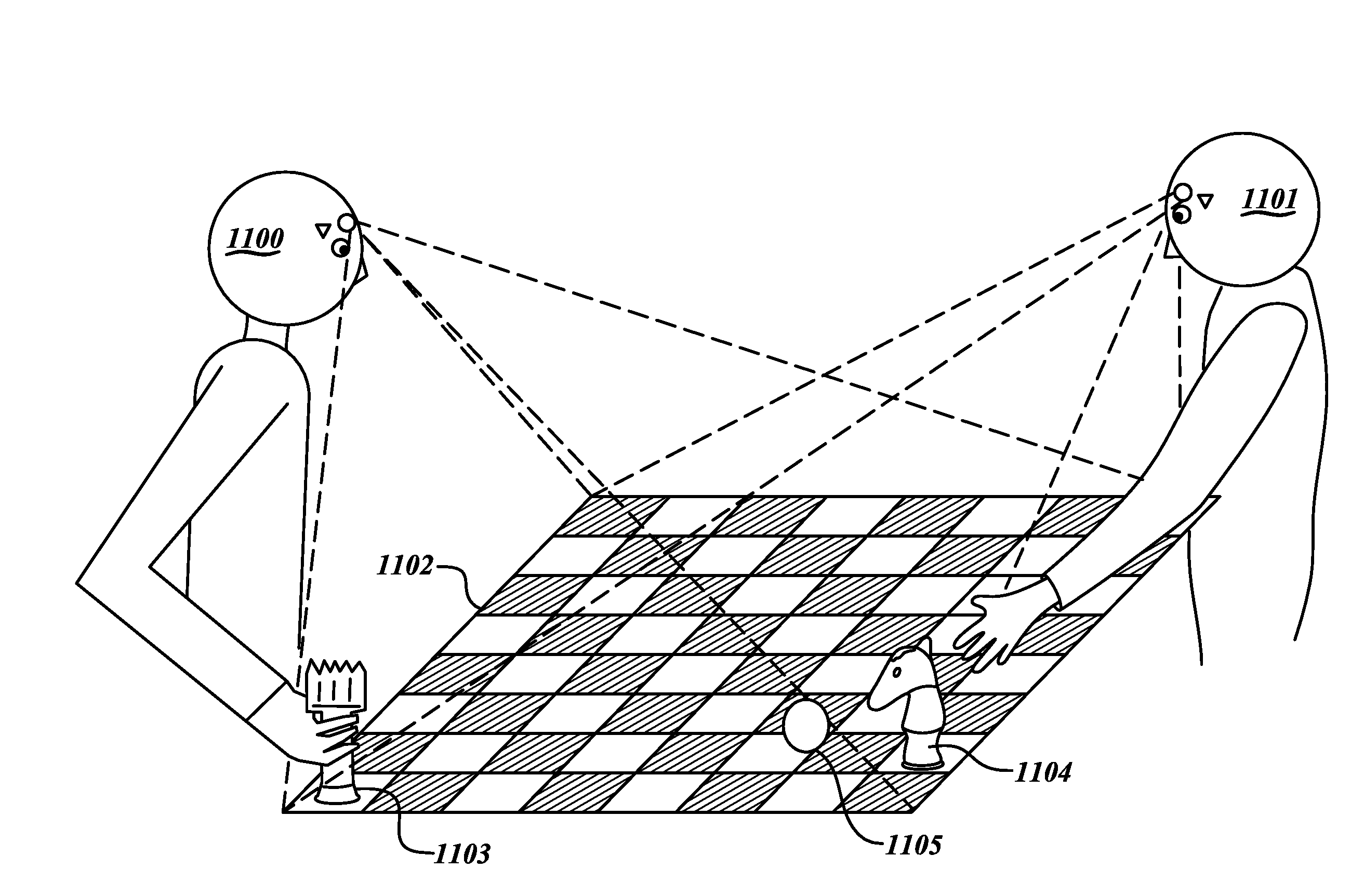
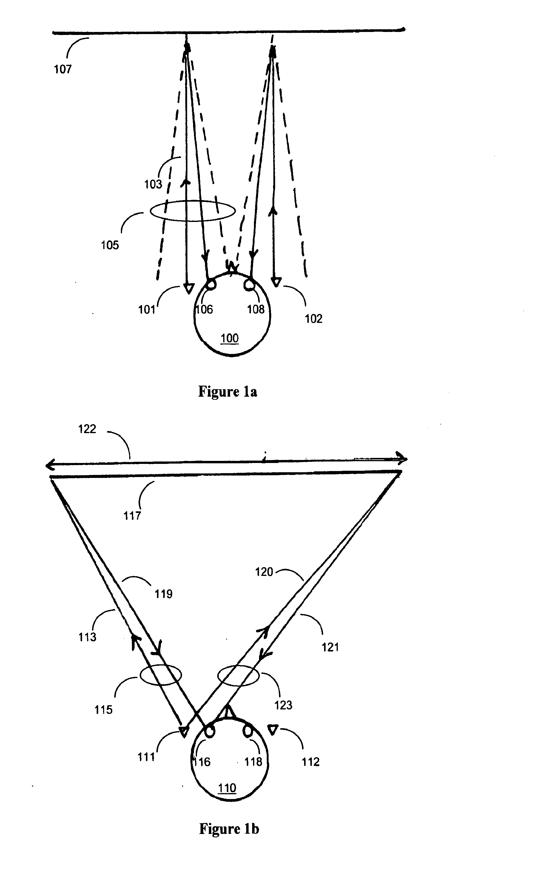
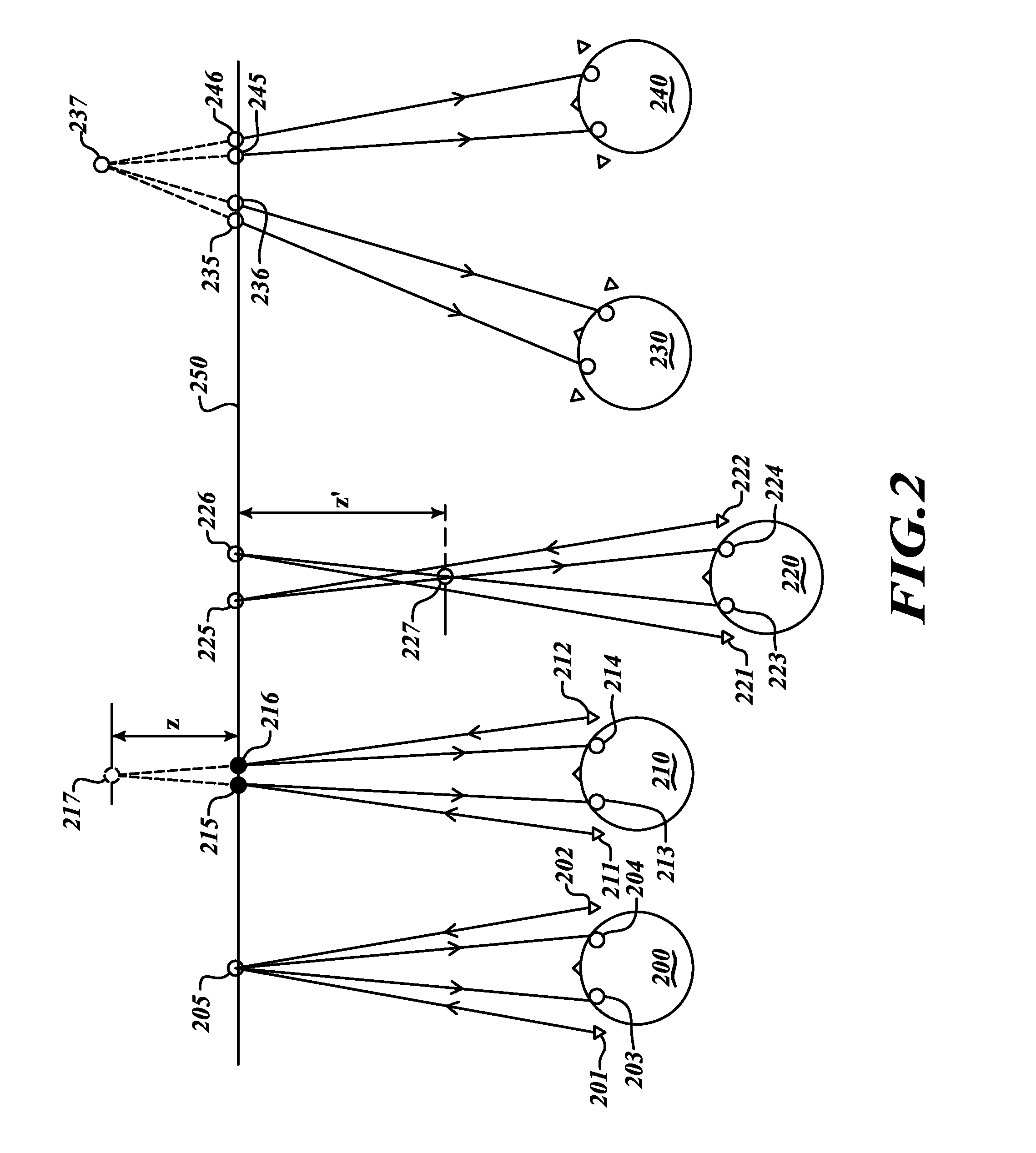
[0061]Two micro projectors each project one image from two separate positions so that the image of each projector can only be seen by one eye. Stereoscopic images are projected with the left image and right image projected separately by each of the projectors. The images are projected onto a retro-reflective screen surface, in such a way that the light from each projector is primarily reflected back to the position of that projector. The left image projector is mounted close to the left eye; its light can only be seen by the left eye. Similarly a right image projector is mounted on the opposite side of the head and its light therefore can only be seen by the right eye.

[0062]A good example of the use of such a system would be for a mobile device user, preferably a smart phone user, by mounting these two projectors on e.g., a headset or glasses (or glasses frame) and placing or unfolding a retro-reflective surface (or “placemat”) on any work surface, su...


PUM


Abstract

A system projects a user-viewable, computer-generated or -fed image, wherein a head-mounted projector is used to project an image onto a retro-reflective surface, so only the viewer can see the image. The projector is connected to a computer that contains software to create virtual 2-D and or 3-D images for viewing by the user! Further, on projector each is mounted on either side of the user's head, and, by choosing for example a retro angle of less than about 10 degrees, each eye can only see the image of one of the projectors at a give distance up to 3 meters, in this example, from the retro-reflective screen. The retro angle used may be reduced with larger viewing distance desired. These projectors use lasers to avoid the need for focusing, and in some cases there projectors use instead of lasers highly collimated LEO light sources to avoid the need for focusing.

Description

CROSS-REFERENCE TO RELATED APPLICATION[0001]This application is a continuation-in-part of U.S. Patent Application Ser. No. 61 / 404,538, filed on Oct. 4, 2010, and claims priority under 35 U.S.C. §119(e) to U.S. Provisional Patent Application Ser. No. 61 / 516,242, filed on Mar. 30, 2011. The subject matter of all of the foregoing is incorporated herein by reference in their entirety.BACKGROUND OF THE INVENTION[0002]1. Field of the Invention[0003]This invention relates generally to personal visualization devices, in some cases with 3-D and / or color.[0004]2. Description of the Related Art[0005]Currently, projection of 3-D video images requires bulky and expensive projection equipment, plus special glasses for the viewer and special theater-quality screens. Thus viewing 3-D videos is an expensive and specialized experience.[0006]As the world becomes more and more mobile, users want the ability to take all kinds of interaction with them. One phenomenon is the emerging craze for tablets. Th...

Claims


Application Information

Patent Timeline
IPC IPC(8): G02B27/01G02B30/26H04N13/363
CPCG03B35/18H04N13/0402H04N13/0452H04N13/0459G02B27/0176H04N13/363H04N13/302H04N13/356G02B5/128G02B2027/0134G02B30/26
Inventor SMITS, GERARD DIRKKIKINIS, DAN
Owner SMITS GERARD DIRK
Why Eureka
Try Eureka