
System and method to estimate location and orientation of an object

a technology of object location and location, applied in the field of methodology and apparatus to determine the location and orientation of objects, to achieve the effect of increasing the accuracy of the system

Inactive Publication Date: 2013-11-14
ENAV MEDICAL
View PDF11 Cites 51 Cited by
  • Summary
  • Abstract
  • Description
  • Claims
  • Application Information

AI Technical Summary

Benefits of technology

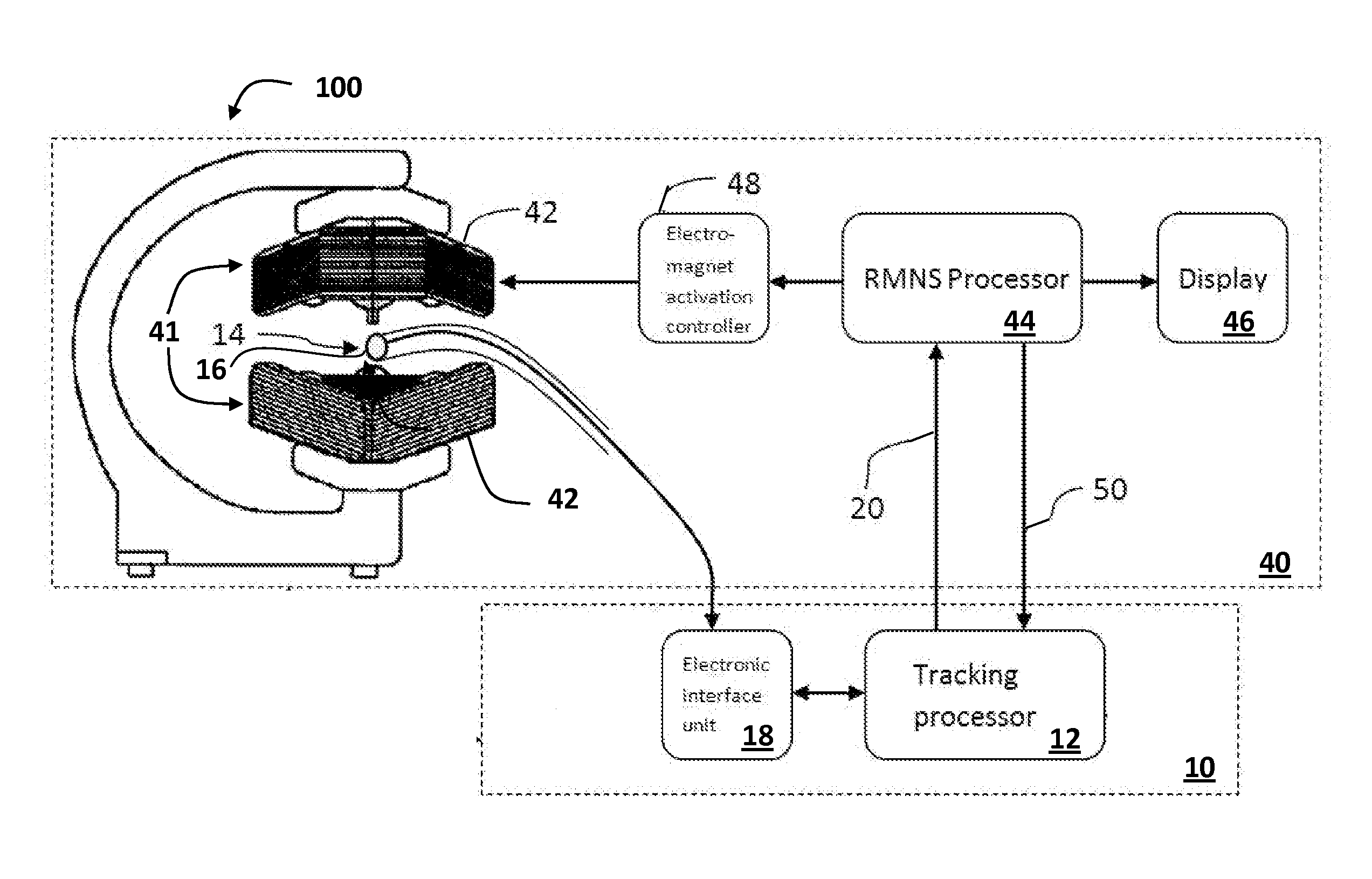
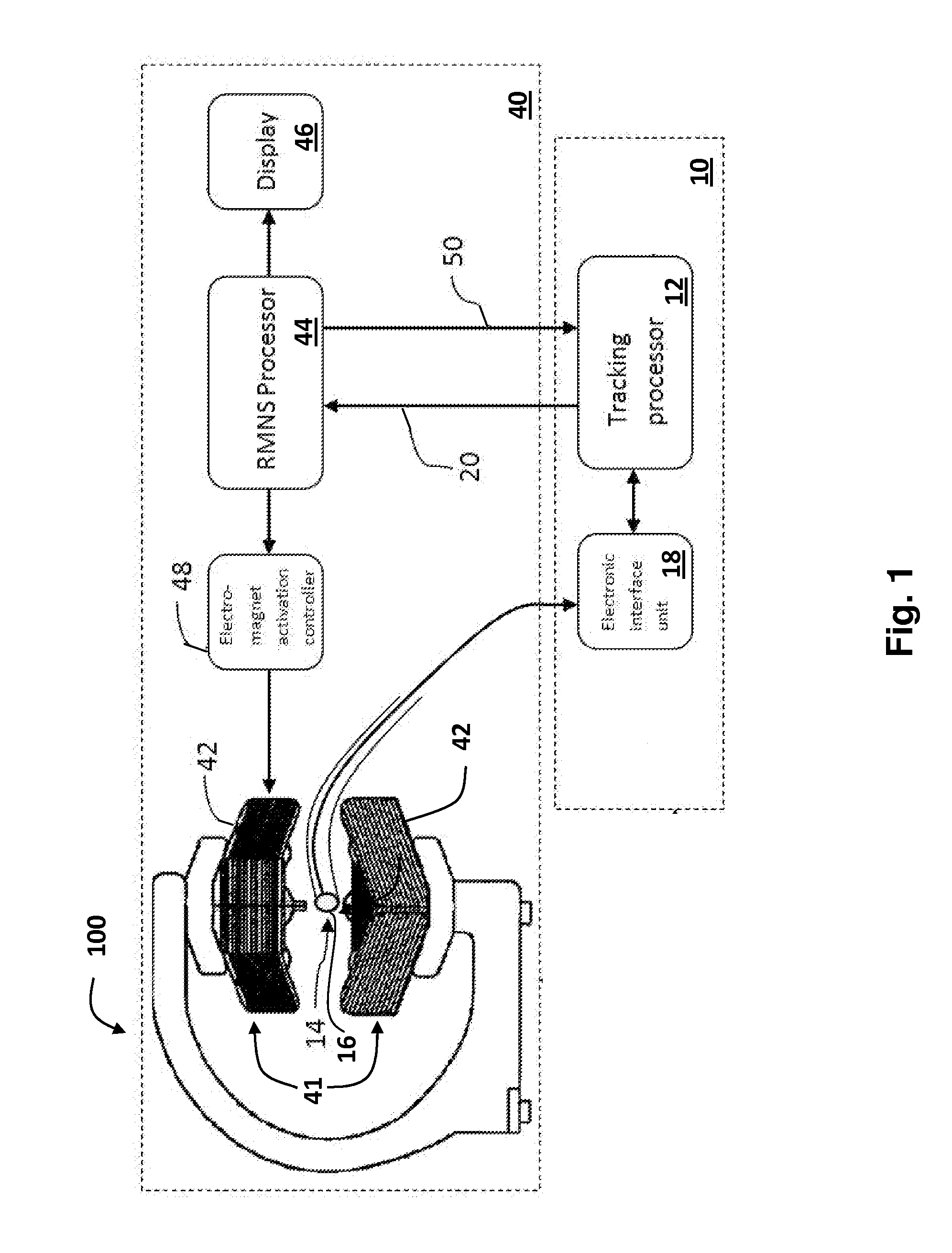
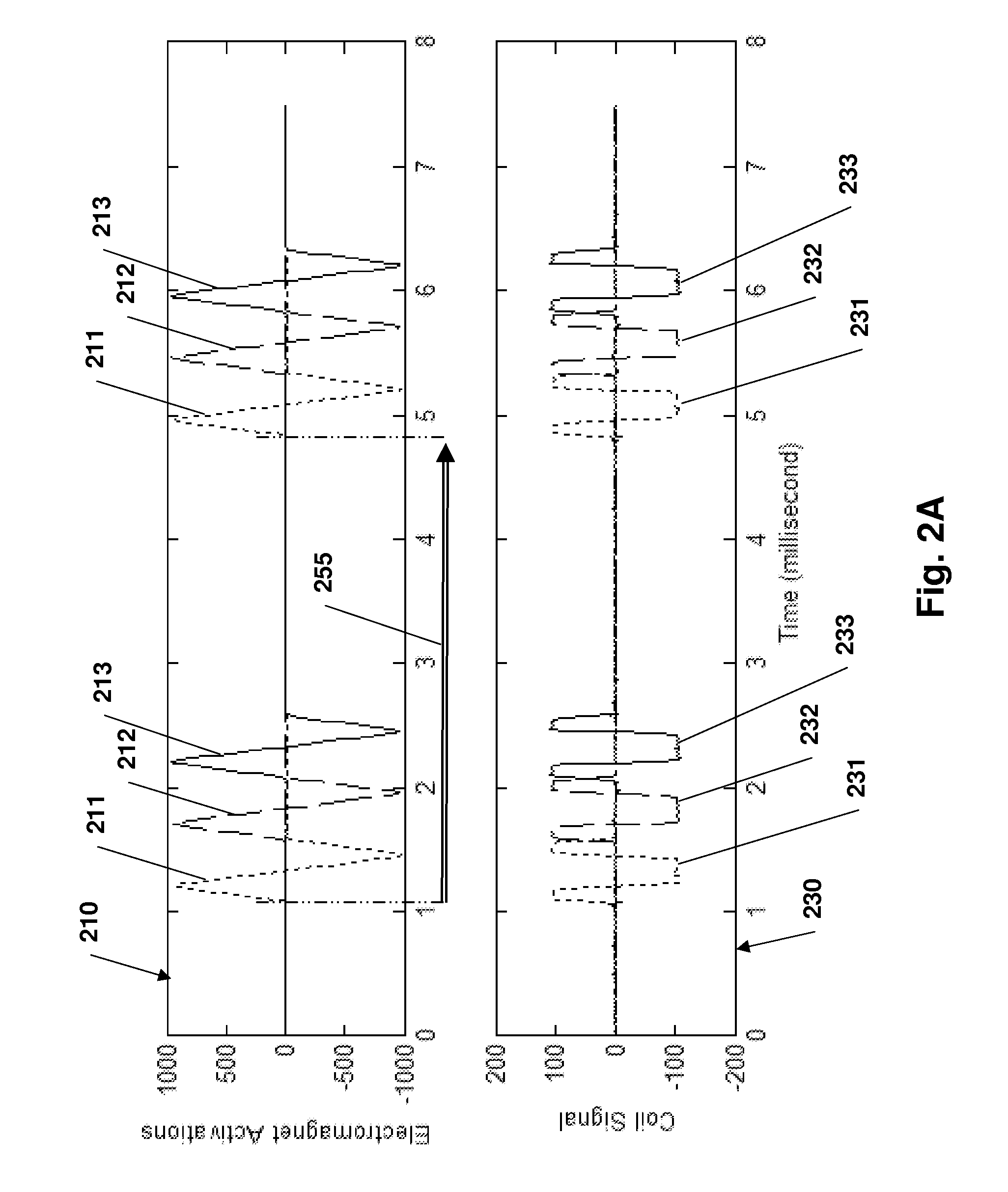
The patent text describes the need for an integrated magnetic navigation and position tracking system that eliminates the need for system registration and thus increases the accuracy of the system. It also describes the need for systems and methods that are capable of providing positioning and orientation of a single coil so as to enable the integration of tracking sensors on the outer surface of guidewires and lumen catheters and to eliminate the need for coordinate system registration. The patent also mentions that the triangular current signal is preferred for activating the sensor coil and that minimizing the differences between the measured responses of the magnetic sensor and the magnetic field map is used to estimate the location and orientation of the sensor.

Problems solved by technology

The CARTO tracking system has several limitations—it uses solid sensors with three orthogonal coils, which cannot be used with lumen catheters or over very small guidewires; it uses electromagnetic coils to generate magnetic fields for tracking, which may interfere with the magnetic coils of the magnetic navigation system; since the magnetic navigation system and the tracking system use different magnetic fields for their tasks, there is a need to register the two coordinate systems (i.e. to define a coordinate transformation between the two systems).

Method used


Image

  • System and method to estimate location and orientation of an object
  • System and method to estimate location and orientation of an object
  • System and method to estimate location and orientation of an object

Examples


Embodiment Construction

[0078]Before explaining at least one embodiment of the invention in detail, it is to be understood that the invention is not necessarily limited in its application to the details set forth in the following description or exemplified by the Examples. The invention is capable of other embodiments or of being practiced or carried out in various ways.

[0079]The terms “comprises”, “comprising”, “includes”, “including”, and “having” together with their conjugates mean “including but not limited to”.

[0080]The term “consisting of” has the same meaning as “including and limited to”.

[0081]The term “consisting essentially of” means that the composition, method or structure may include additional ingredients, steps and / or parts, but only if the additional ingredients, steps and / or parts do not materially alter the basic and novel characteristics of the claimed composition, method or structure.

[0082]As used herein, the singular form “a”, “an” and “the” include plural references unless the context...


PUM


Abstract

A tracking system for estimating the position and orientation of an object inside a patient comprising electromagnets that generate magnetic fields used to navigate an object, including rotating and translating the object, are used to track the position of the object. Position tracking of the object is concurrent with navigating the object; or interleaved with navigating the object. Using the same electromagnets for navigation and tracking ensure coordinate system registration between the navigation system and the position tracking system. A tracking sensor attached to the object comprises at least a single coil generating signals in response to time varying tracking magnetic field generated by the electromagnets. Iterative algorithm is used to estimate position and orientation from sensor's signal. Linearly time varying current in the tracking electromagnets is produced by applying calculated voltage waveform to the electromagnet coils.

Description

FIELD OF THE INVENTION[0001]The present invention relates to methodology and apparatus to determine the location and orientation of an object, for example a medical device, located inside or outside a body of a living subject. More specifically, the invention enables estimation of the location and orientation of various medical devices (e.g. catheters, surgery instruments, endoscopes, untethered capsules, etc.) by measuring electrical potentials induced by time-variable magnetic fields in a sensor having at least one sensing element as a coil. The invention further improves the generation of the magnetic fields required for the determining the location and orientation of the object.BACKGROUND[0002]Remote Magnetic Navigation Systems (RMNS), employed by various companies (e.g. Stereotaxis, Inc.; Magnetecs, Inc.) is an emerging technology for use in catheterization, endoscopy, endoscopic capsule (“video pill”) and other minimally invasive procedures.[0003]Catheters with magnetic tips c...

Claims


Application Information

Patent Timeline
Patent Type & Authority Applications(United States)
IPC IPC(8): A61B5/05
CPCA61B5/05A61B5/062A61B2034/2053A61B34/20
Inventor NEVO, EREZROTH, ABRAHAM
Owner ENAV MEDICAL
Learn More