Imaging system and method

Inactive Publication Date: 2013-11-21
NAT UNIV OF SINGAPORE
View PDF10 Cites 69 Cited by
  • Summary
  • Abstract
  • Description
  • Claims
  • Application Information

AI Technical Summary

Benefits of technology

[0072]The computing means may match the multi-spectral reflectivity of a region of a captured image, as computed by the imaging system, to a mixture of materials with known reflectivity. That mi

Problems solved by technology

Subsequently, the microscope, combining multiple lenses and other elements, brought greater enlarging power, but at the cost of poorer depth cues.
Since the operator must place an eye exactly at the eyepiece, head motion needed for parallax is not possible.
Although weaker depth cues, such as a near object obscuring a more distant object, may still be provided to the operator, positioning a tool, precisely in the depth direction may not be possible.
However, the human brain can still not reconstruct depth, and guiding micro-tools remains difficult.
The stereo microscope restored binocular depth perception, but parallax remains unavailable, because the operator's head must remain stationary at the eyepieces.
Operators, such as micro-surgeons and those assembling microscopic electronic parts, without s

Method used


Image

  • Imaging system and method
  • Imaging system and method
  • Imaging system and method

Examples


Embodiment Construction

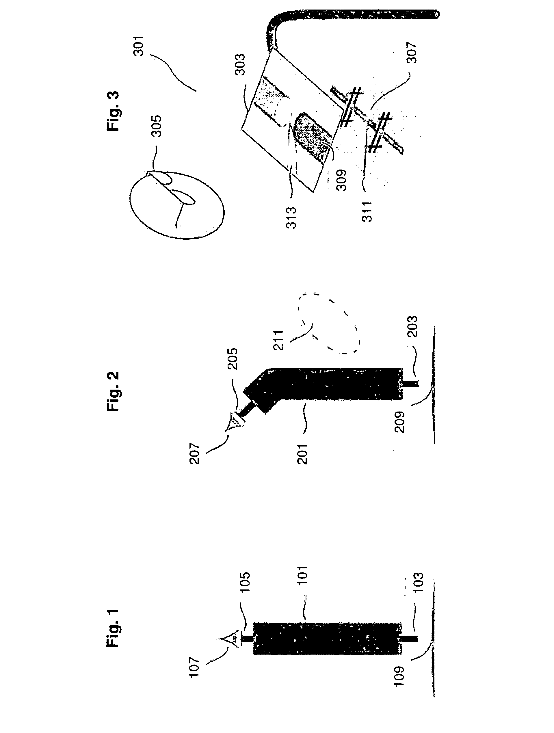
[0088]In the prior art system shown in FIG. 3, the long-barrelled cameras, whose geometry was described as compensated by mirrors, can now be replaced by cameras flat enough to be placed directly under the display screen 303, facing the work site. An example of such a thin system which enables “a 3D depth map without the need for active illumination or calibration” is described by K. Fife, A. El Gamal and H-S. P. Wong, in “A 3 M Pixel Multi-Aperture Image Sensor with 0.7 μm Pixels in 0.11 μm CMOS”, IEEE ISSCC Digest of Technical Papers, pp. 48-49, February 2008, the details of which are hereby incorporated by reference. The small differences between the light captured by the different apertures in that device allow computation of depth data. This is analogous to the use of greater differences in the views by physically separate eyes or cameras. After the depth computation, each pixel of the processed image has a depth associated with it. This illustrates that images with depth data ...


PUM


Abstract

There is provided an imaging system comprising image capture apparatus and display apparatus. The image capture apparatus is for capturing an image of an operator work site, the image including depth information. The display apparatus is in communication with the image capture apparatus, and comprises at least one display screen. The display apparatus is arranged to receive the image captured by the image capture apparatus, including the depth information, and display to the operator the image captured by the image capture apparatus, including the depth information, on the display screen. The display screen is located between the operator's eyes and the position of the work site. There is also provided a method for capturing and displaying an image of an operator work site.

Description

FIELD OF THE INVENTION[0001]The present invention relates to the fields of microscopy and digital interaction and display. In particular, the present invention relates to an imaging system for capturing and displaying an image of an operator work site.BACKGROUND TO THE INVENTION[0002]Seeing small objects enlarged, and working on those objects, began with the lens. A large lens presents paired distinct views (a stereo image) to the two eyes of an operator, and a change in view (parallax) when the operator's head moves. These two depth cues are powerful for the human vision system, and enable the operator to obtain a strong three-dimensional sense of the object behind the lens. Such depth cues are important if the operator is to manipulate objects such as tools. It must be possible to position a tool correctly in the depth direction, as well as move the tool correctly across the image in the length and width directions.[0003]Subsequently, the microscope, combining multiple lenses and ...

Claims


Application Information

Patent Timeline
IPC IPC(8): H04N13/02
CPCH04N13/0203A61B1/00048G02B21/22A61B8/0841A61B8/467A61B8/461A61B8/468H04N13/156H04N13/204H04N13/271H04N13/279H04N13/344H04N13/383
Inventor RAPPEL, JAMES KOLENCHERYPOSTON, TIMOTHYLIM, BENG HAI
Owner NAT UNIV OF SINGAPORE
Why Eureka
Try Eureka