
Image processing apparatus, image pickup apparatus, image processing method, and image processing program

a technology of image processing and image pickup, applied in the field of digital image processing, can solve the problems of image quality after blurring, inability to obtain an image, and difficulty in reducing the size of the camera, and achieve the effect of high quality

Inactive Publication Date: 2013-11-21
CANON KK
View PDF1 Cites 15 Cited by
  • Summary
  • Abstract
  • Description
  • Claims
  • Application Information

AI Technical Summary

Benefits of technology

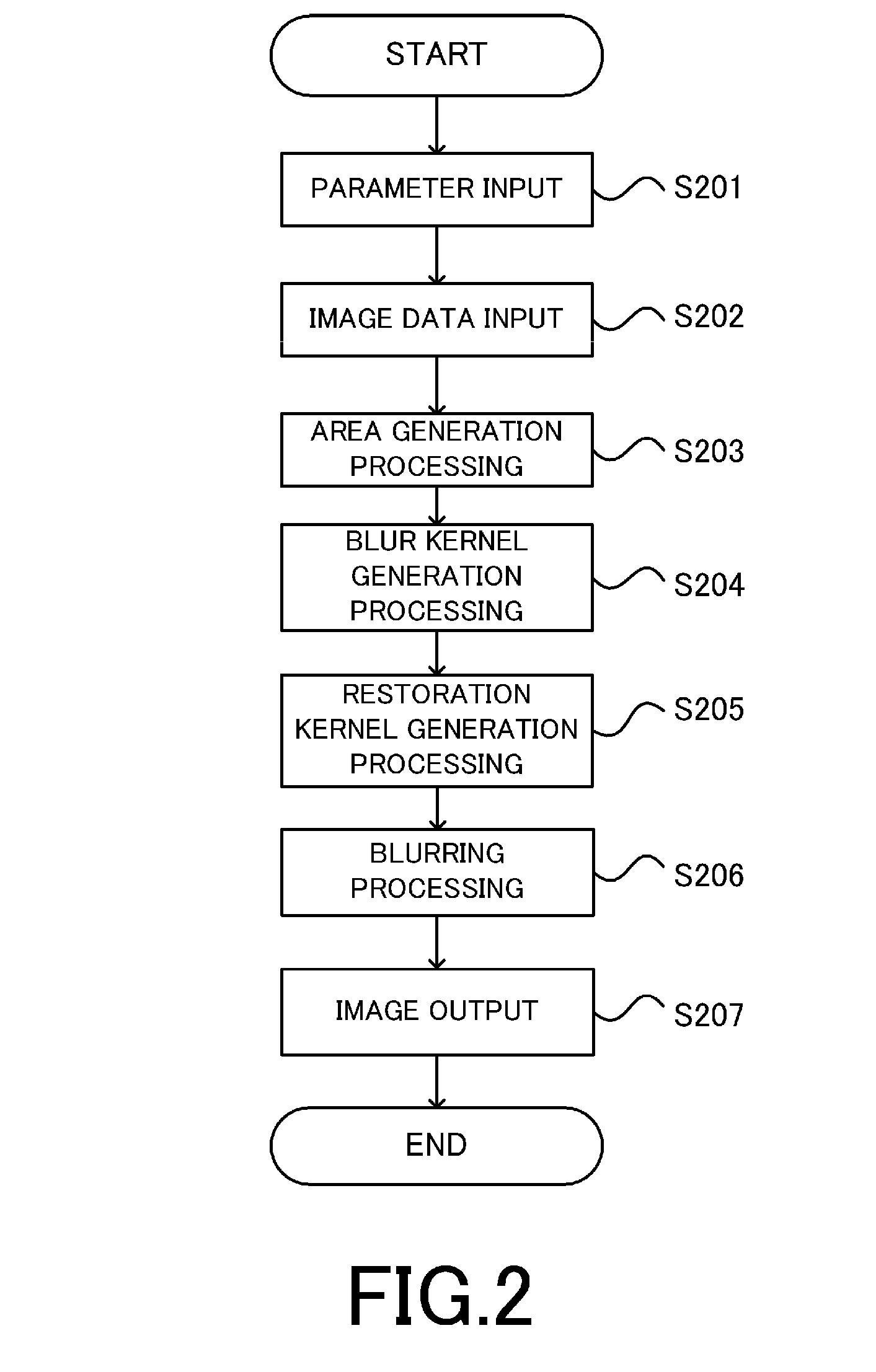
The present invention provides an image processing apparatus, method, and program that can generate a high-quality blurred image without the influence of diffraction or aberration. The apparatus includes a restoration kernel acquisition section, a blur kernel acquisition section, and an image processing section. The restoration kernel is used to eliminate degradation of the image, while the blur kernel is used to blur the image. The image processing section combines the restoration kernel and blur kernel to achieve the desired blurred image. Additionally, the invention provides a method for blurring the image based on distance information on the subject. Overall, the invention allows for improved image quality and a better user experience.

Problems solved by technology

However, when the size of the image sensor is increased, the size of an image-forming optical system is also increased so that it becomes difficult to reduce the size of the camera.
However, even when the deep-focus image is to be picked up, in reality, it is not possible to obtain an image which is perfectly focused in all areas due to influences of diffraction caused by an aperture and image plane aberration, and a difference in object distance.
In a case where blurring processing in which the focus position of a picked-up image is changed is performed, when the picked-up image is not a strictly deep-focus image, there arises a problem that the image quality after the blurring is degraded, i.e., apart that should be in focus is blurred.
In addition, there is a problem that, even in the part in focus, the image is degraded by the influence of the diffraction or aberration and a blurred image having high image quality cannot be obtained.

Method used


Image

  • Image processing apparatus, image pickup apparatus, image processing method, and image processing program
  • Image processing apparatus, image pickup apparatus, image processing method, and image processing program
  • Image processing apparatus, image pickup apparatus, image processing method, and image processing program

Examples


first embodiment

[0022]Hereinbelow, a description will be given of an image processing apparatus as one aspect of the present invention with reference to the drawings. Like reference numeral in each drawing denote like means. Note that the scope of the present invention is not intended to be limited to examples shown in the description of the embodiments.

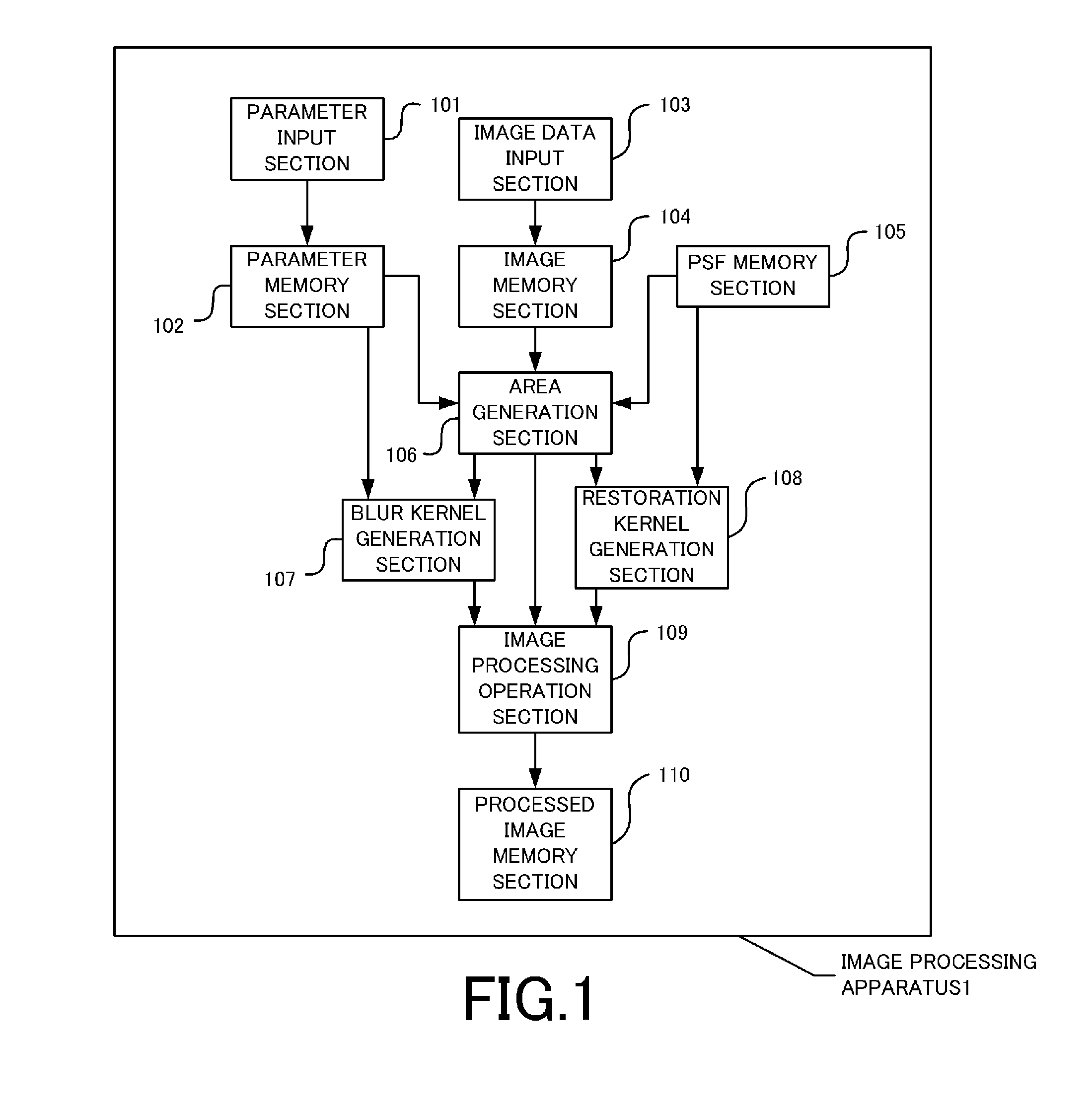
[0023]FIG. 1 is a system configuration view of an image processing apparatus according to a first embodiment.

[0024]An image processing apparatus 1 has a parameter input section 101, a parameter memory section 102, an image data input section 103, an image memory section 104, a PSF memory section 105, and an area generation section 106. In addition, the image processing apparatus 1 also has a blur kernel generation section 107, a restoration kernel generation section 108, an image processing operation section 109, and a processed image memory section 110.

[0025]The image processing apparatus according to the present embodiment may be implemented by us...

second embodiment

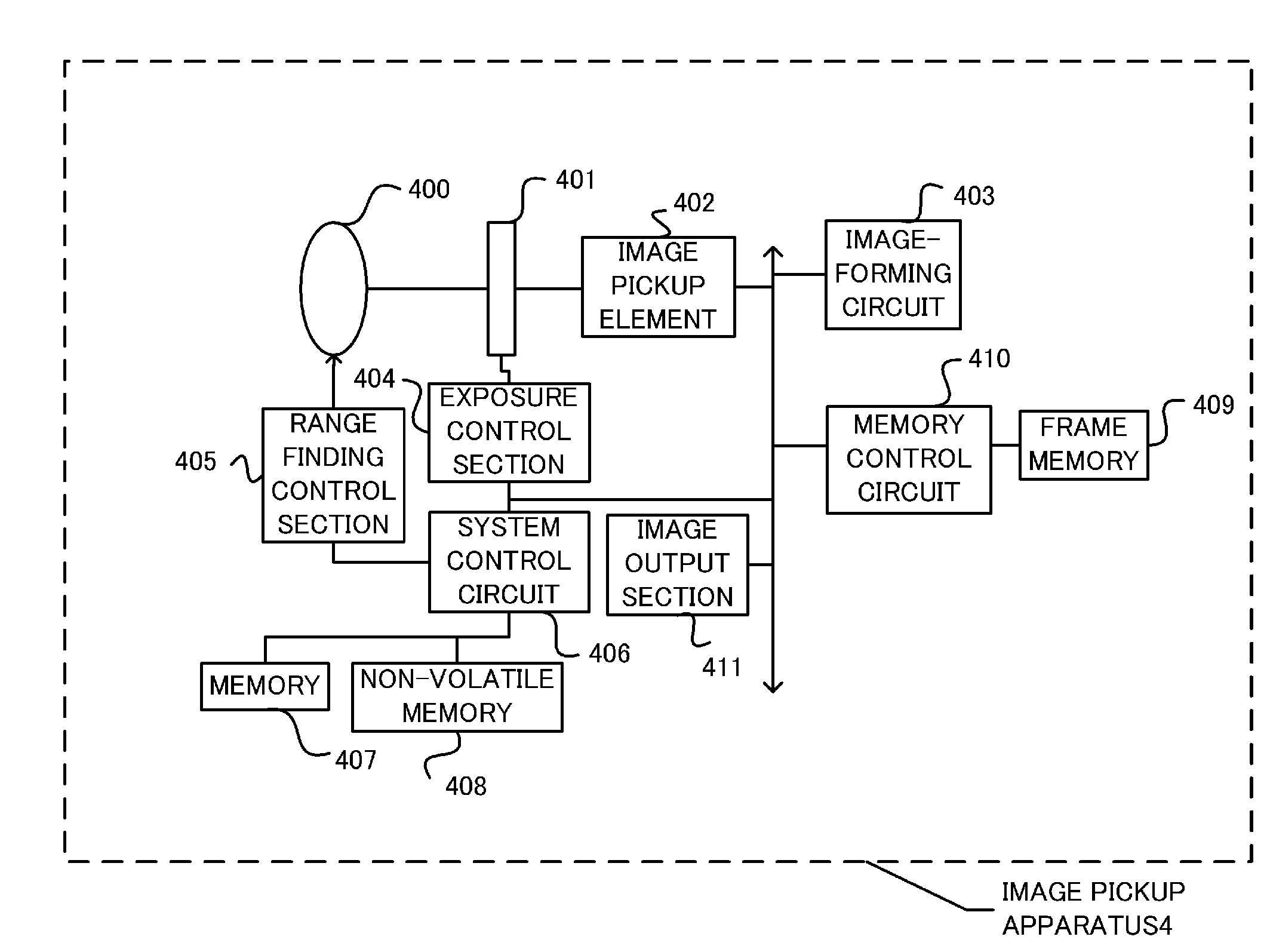
[0069]An image pickup apparatus according to a second embodiment is an image pickup apparatus including the image processing apparatus 1 according to the first embodiment. FIG. 7 shows the configuration of the image pickup apparatus according to the present embodiment. An image pickup apparatus 4 is typically a digital still camera, a digital video camera, or the like.

[0070]In FIG. 7, the reference numeral 400 denotes an image pickup lens that guides a subject light to an image pickup element 402. The reference numeral 401 denotes an exposure control element including a diaphragm and a shutter. The subject light having entered via the image pickup lens 400 enters into the image pickup element 402 via the exposure control element 401. The image pickup element 402 is an image pickup element that converts the object light to an electric signal and outputs the electric signal, and is constituted by an image sensor such as a CCD or a CMOS.

[0071]An image-forming circuit 403 is a circuit f...

third embodiment

[0078]A third embodiment is an embodiment in which the kernel similarity I in the first embodiment is determined based on a visual spatial frequency characteristic in addition to the frequency characteristic of the kernel.

[0079]The present embodiment is different from the first embodiment only in the calculation method of the kernel similarity in Steps S301 and S302. The configuration and the processing method are otherwise the same as those in the first embodiment.

[0080]In the present embodiment, the kernel similarity is calculated by using the visual spatial frequency characteristic in addition to the MTF of each of the blur kernel and the restoration kernel. As an example, a value called a cascaded modulation transfer acutance (CMTA) is used. The CMTA is described in detail in “TAKAGI Mikio, SHIMODA Haruhisa, “Handbook of Image Analysis (Revised Edition)”, University of Tokyo Press, p. 77-78, 2004”.

[0081]It is possible to determine the shift-invariant area by using the method des...


PUM


Abstract

An image processing apparatus that blurs a picked-up image based on distance information on a subject, comprises a restoration kernel acquisition section that acquires a restoration kernel as a kernel for eliminating degradation of an image; a blur kernel acquisition section that acquires a blur kernel as a kernel for blurring the image; a compound kernel acquisition section that acquires a compound kernel obtained by merging the restoration kernel with the blur kernel; and an image processing section that eliminates the degradation of the picked-up image and blurs the picked-up image by using the compound kernel.

Description

BACKGROUND OF THE INVENTION[0001]1. Field of the Invention[0002]The present invention relates to digital image processing, and particularly relates to an image processing technology that performs blurring on an image.[0003]2. Description of the Related Art[0004]In recent years, there is proposed a compact digital camera capable of obtaining an excellent blur by increasing the size of an image sensor. However, when the size of the image sensor is increased, the size of an image-forming optical system is also increased so that it becomes difficult to reduce the size of the camera. To cope with this, Japanese Patent Application Laid-open No. 2000-207549 discloses a camera in which blurring is performed by picking up an image that is nearly in deep focus (a state where all areas are in focus), acquiring information on the distance to a subject, and performing predetermined image processing on the picked-up image.[0005]However, even when the deep-focus image is to be picked up, in realit...

Claims


Application Information

Patent Timeline
Patent Type & Authority Applications(United States)
IPC IPC(8): H04N5/225
CPCH04N5/225H04N25/615H04N23/00
Inventor TANAKA, SHIN
Owner CANON KK
Learn More