Machining vibration suppressing method and machining vibration suppressing apparatus for machine tool

a technology of machining vibration and suppressing apparatus, which is applied in the direction of process control, machine control, instruments, etc., can solve the problems of affecting the quality of machine tools, and requiring a unit that applies minute vibration, so as to suppress and reliably suppress tool chipping. , the effect of suppressing chatter vibration and tool chipping

Active Publication Date: 2013-11-21
OKUMA CORP
View PDF9 Cites 29 Cited by
  • Summary
  • Abstract
  • Description
  • Claims
  • Application Information

AI Technical Summary

Benefits of technology

[0026]According to the construction, two types of vibration including vibration synchronized with the rotation speed of the tool and vibration shifted therefrom are applied to the workpiece, thereby suppressing chatter vibration and tool chipping as well.
[0027]According to the present invention, the workpiece is machined while applying forced vibration to feed operation, that is, while relatively vibrating the workpiece, which periodi

Problems solved by technology

In a machine tool that performs machining while rotating a tool, chatter vibration is caused when the amount of cutting is increased during machining to result in a degraded machined surface.
However, the method for milling in which an optimum rotation speed is calculated requires a sensor that detects chatter and a complicated control device.
In the method for cutting in which the rotation speed of the main spindle is varied by a certain amount of displacement and a certain period, an excessive load is applied to the main spindle motor.
The method in w

Method used


Image

  • Machining vibration suppressing method and machining vibration suppressing apparatus for machine tool
  • Machining vibration suppressing method and machining vibration suppressing apparatus for machine tool
  • Machining vibration suppressing method and machining vibration suppressing apparatus for machine tool

Examples


Embodiment Construction

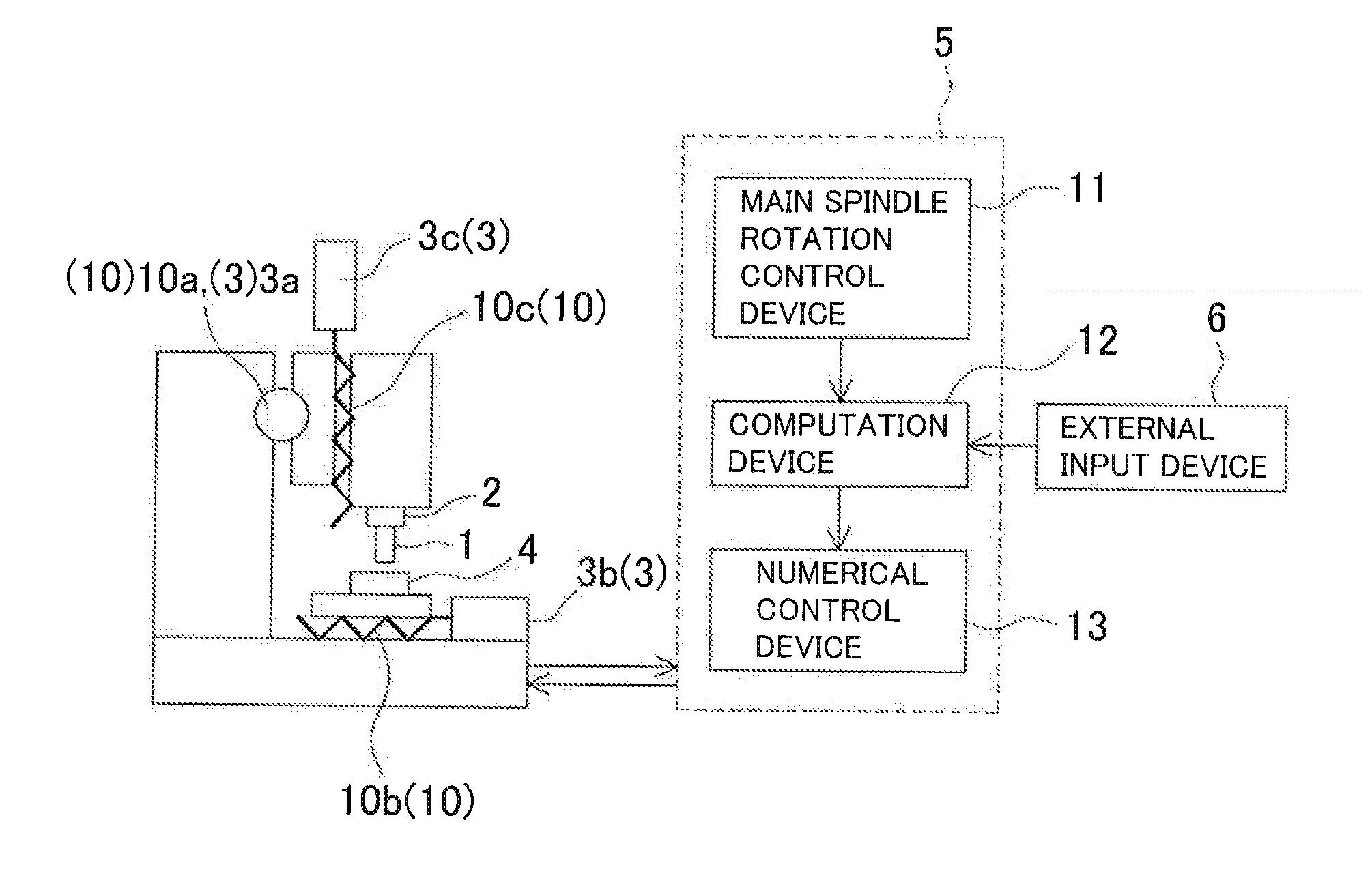
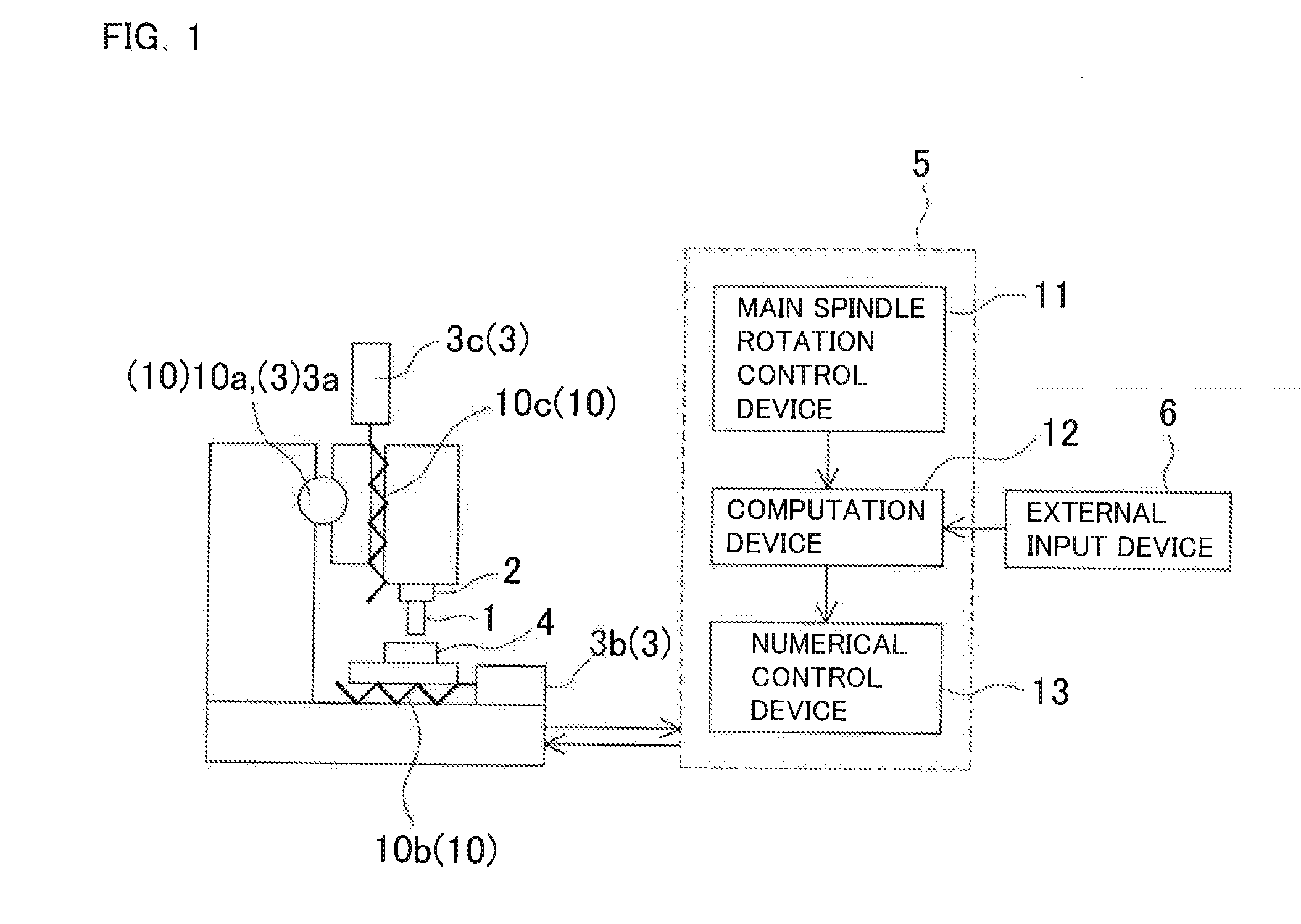
[0039]An embodiment of the present invention will be described in detail below with reference to the drawings. FIG. 1 is a diagram showing an example of a machine tool including a machining vibration suppressing apparatus according to the present invention. Reference numeral 1 denotes a tool, 2 denotes a main spindle that rotates the tool 1, 3 denotes a feed shaft drive unit that controls the feed rate of a feed shaft 10, 4 denotes a workpiece, 5 denotes a machining vibration suppressing apparatus, and 6 denotes an external input device that allows input of conditions such as command values for the radius, the angular velocity, and the phase difference of vibration to be superimposed on the feed shaft 10, information on cutting edges, and so forth.

[0040]The feed shaft drive unit 3 includes an X-axis control unit 3a that controls an X-axis feed shaft 10a, a Y-axis control unit 3b that controls a Y-axis feed shaft 10b, and a Z-axis control unit 3c that controls a Z-axis feed shaft 10c...


PUM

PropertyMeasurementUnit
Frequencyaaaaaaaaaa
Angular velocityaaaaaaaaaa

Abstract

An apparatus includes an external input device that allows setting of the amount of runout and the phase of each cutting edge, a computation device that acquires the rotational phase of a tool and that computes the angular velocity and the phase of vibration of two, X-axis and Y-axis, feed shafts on the basis of the input amount of runout and angular velocity of each cutting edge to generate a feed shaft control signal, and a numerical control device that controls feed in the X-axis and the Y-axis directions. The numerical control device relatively vibrates a workpiece in synchronization with the angular velocity of the tool on the basis of the results of computation performed by the computation device.

Description

BACKGROUND OF THE INVENTION[0001]This application claims the benefit of Japanese Patent Application Number 2012-113633 filed on May 17, 2012, the entirety of which is incorporated by reference.TECHNICAL FIELD[0002]The present invention relates to a machining vibration suppressing method and a machining vibration suppressing apparatus for a machine tool capable of suppressing occurrence of chatter vibration and tool chipping during milling and cutting, in particular during deep cutting such as rough machining.BACKGROUND ART[0003]In a machine tool that performs machining while rotating a tool, chatter vibration is caused when the amount of cutting is increased during machining to result in a degraded machined surface. In order to suppress such chatter during machining, there has been proposed a technique, for milling, in which an optimum rotation speed is calculated from the eigenfrequency of vibration of the system in which the chatter is caused and the chatter frequency during machi...

Claims


Application Information

Patent Timeline
IPC IPC(8): B23Q17/09
CPCB23Q17/0976B23Q11/0039G05B19/404G05B2219/37517G05B2219/49176Y10T409/304312Y10T409/303808Y10T409/303752Y10T409/306832B23Q15/013B23Q15/08
Inventor INAGAKI, HIROSHISHIKAMA, TOSHIYA
Owner OKUMA CORP
Why Eureka
Try Eureka