Observation system, recording medium, and control method of observation system

a technology of observation system and recording medium, which is applied in the field of observation system, recording medium and control method of observation system, can solve the problems of difficult to conduct observation from the time of emergence of a cell mass, difficult to adjust the cell mass to the field of view, and high time and effort required for cell observation using a microscop

Active Publication Date: 2013-11-21
PHC HLDG CORP
View PDF5 Cites 7 Cited by
  • Summary
  • Abstract
  • Description
  • Claims
  • Application Information

AI Technical Summary

Problems solved by technology

However, observation of cells using a microscope requires much expense in time and effort.
In micro observation, a narrow field of view causes difficulty in searching a target cell mass, and also causes difficulty in adjusting the cell mass to the field of view.
Further, in observation that is conducted at the time of replenishment or replacement of culture fluid in a culture container usually once in one to three days, it is difficult to conduct observation from a time of emergence of a cell mass, and thus a technique capable of observation of a cell mass from the time of emergence thereof is in high demand.
Further, in picking up an image of a cell in each of the cases where the entire container is observed and where a part of the interior of the container is observed under magnification, such a problem that heat generated from illumination and a lens driving system, for example, has effects on growth of the cell arises.
However, it is not easy to manually detect an observation target cell mass in the entire container.
However, in that case, image processing for detecting the observation target cell mass from the macro observation image is complicated and requires processing time of several minutes depending on the number of pixels of the macro observation image.
Thus, a work of individually detecting those cell masses through image processing and picking up an image of each of them needs to be carried out repeatedly, which causes prolonged observation time.

Method used


Image

  • Observation system, recording medium, and control method of observation system
  • Observation system, recording medium, and control method of observation system
  • Observation system, recording medium, and control method of observation system

Examples


first embodiment

Entire Configuration

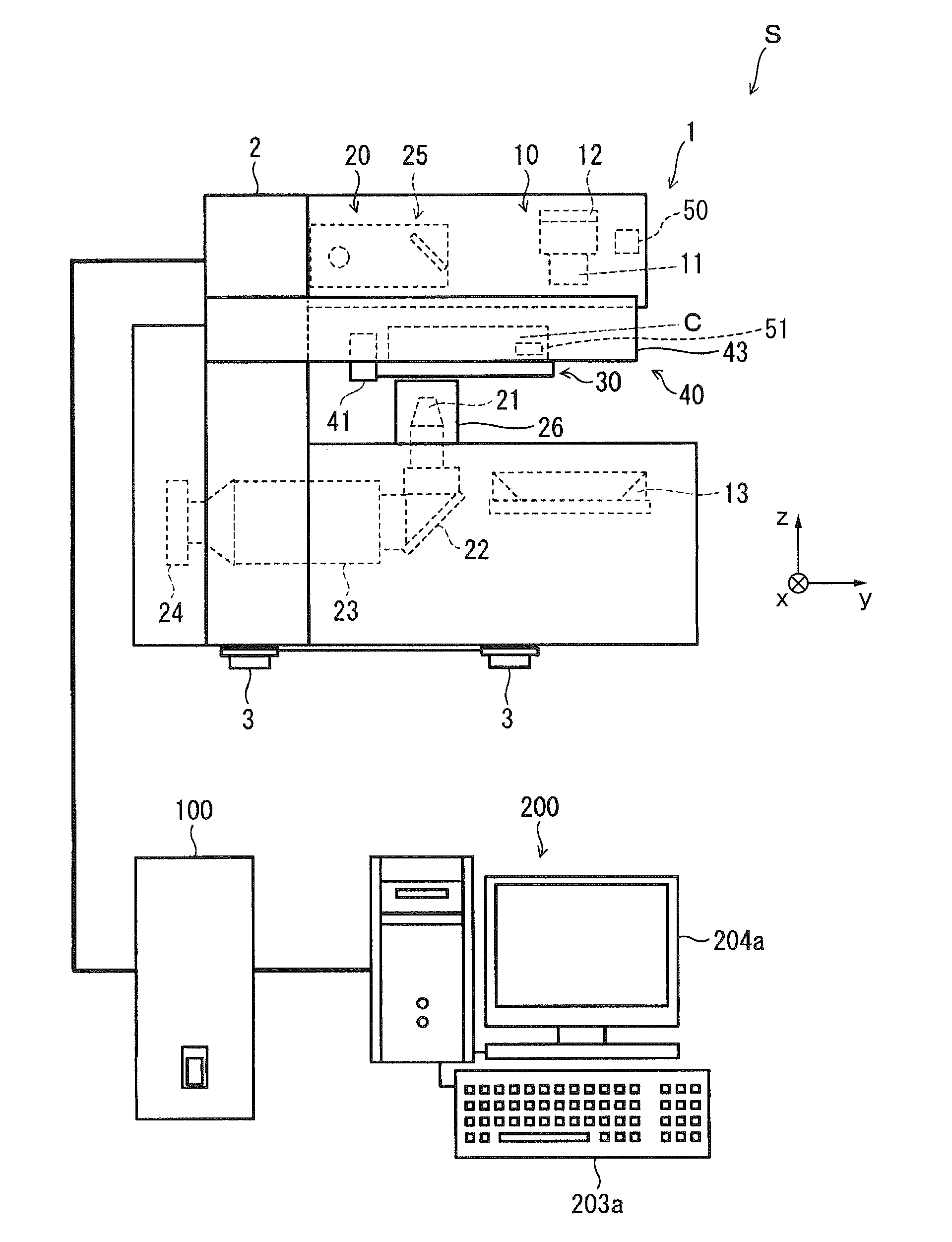
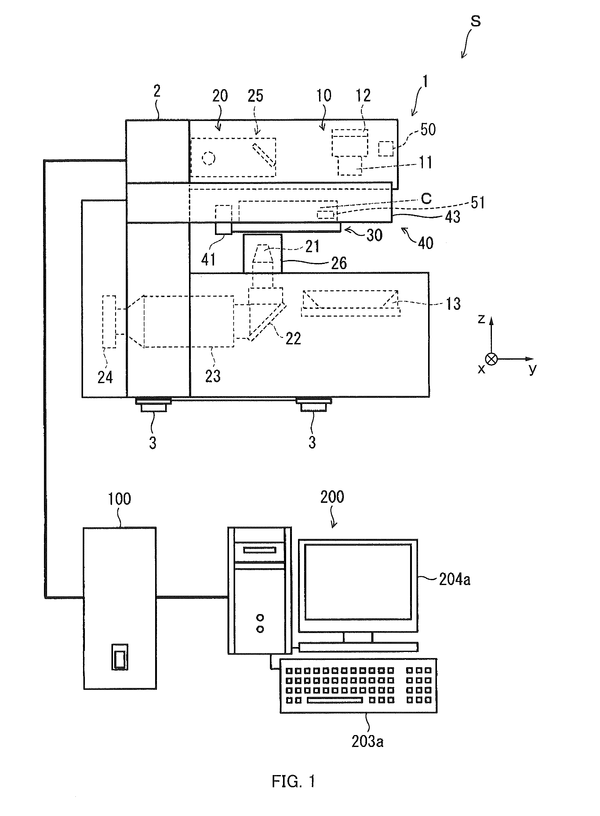
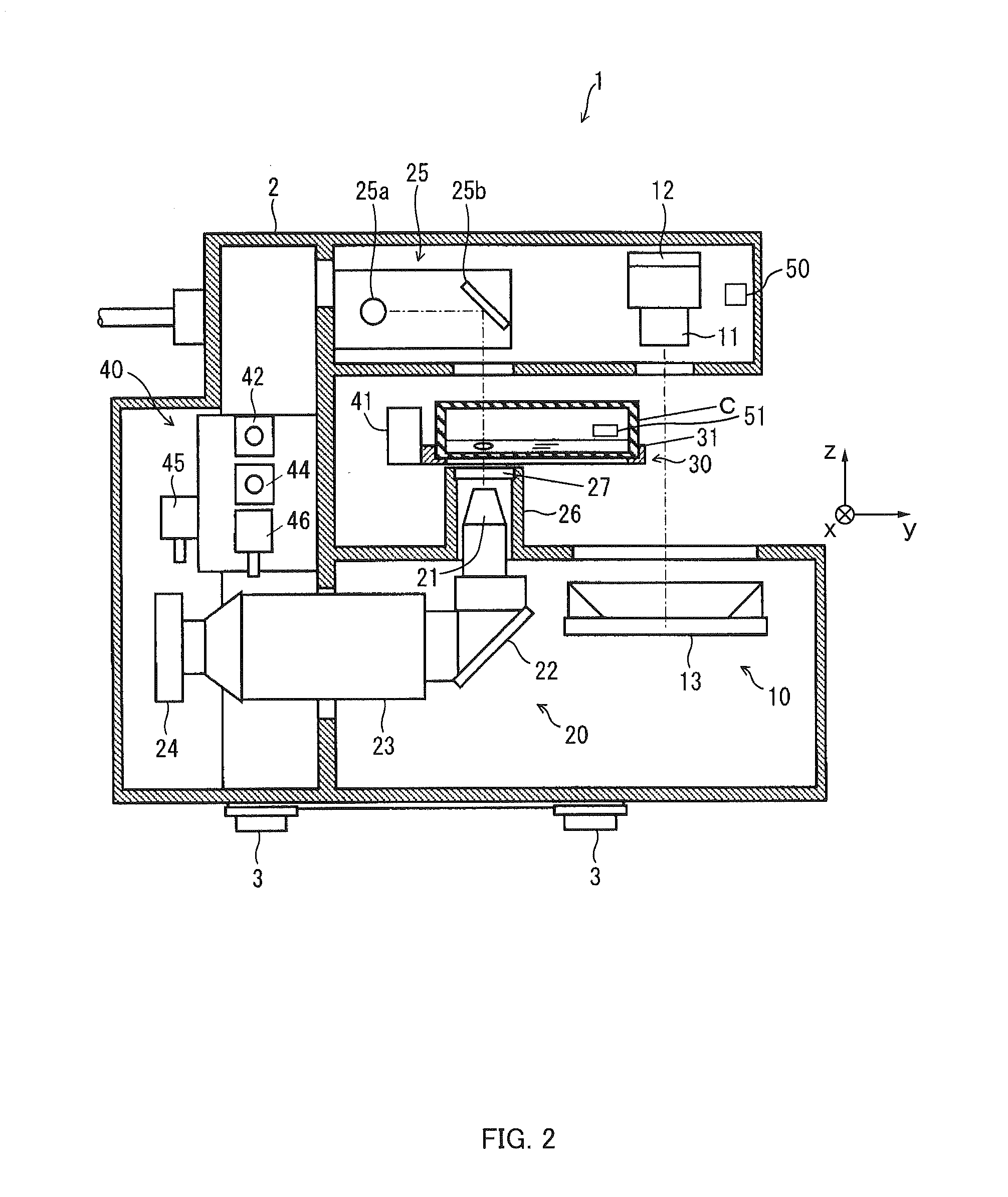
[0031]An observation system S according to a first embodiment of the present invention will be described with reference to FIGS. 1 to 6. FIG. 1 is an entire configuration diagram of the observation system S, FIG. 2 is a perpendicular sectional side view of an observation apparatus 1 included in the observation system S, FIG. 3 is a perpendicular sectional front view of the observation apparatus 1, FIG. 4 is a perpendicular sectional side view of the observation apparatus 1, and FIG. 5 is a block diagram illustrating a configuration of a computer 200 included in the observation system S. FIG. 6 is a diagram illustrating an observation history table.

[0032]As illustrated in FIG. 1, the observation system S includes, for example, the observation apparatus 1, a control device 100, and the computer 200. Further, in FIG. 1, constituent elements built in the observation apparatus 1 and not seen from the outside are indicated by a broken line.

[0033]In the following descri...

second embodiment

[0192]Next, a description will be given of a configuration of the observation system S according to a second embodiment of the present invention with reference to FIG. 10. FIG. 10 is a configuration diagram of the observation system S. Note that since a basic configuration of this embodiment is the same as that of the aforementioned first embodiment described with reference to FIGS. 1 to 9, the same reference numerals are given to the constituent elements common to those in the first embodiment, and the figures and the descriptions thereof will be omitted.

[0193]The observation apparatus 1 of the observation system S according to a second embodiment of the present invention is included in the interior of an incubator 300, as illustrated in FIG. 10. The incubator 300 is an example of a storage case for culturing or storing a cell, and forms a biologically and / or physically sealed storage space E. The observation apparatus 1 is installed on a shelf 301 provided in the interior of the i...

third embodiment

[0196]Next, a description will be give of a configuration of the observation system. S according to a third embodiment of the present invention with reference to FIGS. 11 and 12. FIG. 11 is a configuration diagram of the observation systems, and FIG. 12 is a partial sectional side view of an isolator illustrated in FIG. 11. Note that since a basic configuration of this embodiment is the same as that of the aforementioned first embodiment described with reference to FIGS. 1 to 9, the same reference numerals are given to the constituent elements common to those in the first embodiment and the figure and the descriptions thereof will be omitted.

[0197]The observation apparatus 1 of the observation system S according to the third embodiment is housed in the interior of an isolator 400 as illustrated in FIGS. 11 and 12.

[0198]The isolator 400 includes a case 402 at the substantially center part of a main body 401. The case 402 forms a working space F sealed biologically and / or physically f...


PUM

PropertyMeasurementUnit
timeaaaaaaaaaa
humidityaaaaaaaaaa
temperatureaaaaaaaaaa

Abstract

An observation system to observe a sample mass formed of samples gathering in a container containing the samples and a solution, includes: an entire image pickup unit to image the entire container; a sample mass identification unit to identify a sample mass formed in the container, from a macro observation image obtained by imaging the entire container; a magnifying image pickup unit to magnify and image a part of an area in the container including the sample mass identified by the sample mass identification unit; and a history information storage unit to store position information of the sample mass in association with time and date information, wherein the magnifying image pickup unit magnifies and images a part of an area in the container based on the past position information stored in the history information storage unit, while the sample mass identification unit is executing processing of identifying the sample mass.

Description

CROSS-REFERENCE TO RELATED APPLICATIONS[0001]This application is a continuation under 35 U.S.C. §120 of PCT / JP2012 / 080381, filed Nov. 22, 2012, which is incorporated herein reference and which claimed priority to Japanese Application No. 2011-281559, filed Dec. 22, 2011. The present application likewise claims priority under 35 U.S.C. §119 to Japanese Application No. 2011-281559, filed Dec. 22, 2011, the entire content of which is also incorporated herein by reference.BACKGROUND OF THE INVENTION[0002]1. Field of the Invention[0003]The present invention relates to an observation system, a recording medium, and a control method of observation system.[0004]2. Description of the Related Art[0005]In culturing cells, if observation can be started concurrently with emergence of a cell mass having a plurality of cells gathering therein and the observation can be conducted sequentially in chronological order, it can be a promising technique to support regenerative medicine, for example. Such...

Claims


Application Information

Patent Timeline
Patent Type & Authority Applications(United States)
IPC IPC(8): C12Q1/02
CPCC12Q1/02C12M41/36G01N2015/1006G01N15/1463
Inventor NAKAMURA, AKIRA
Owner PHC HLDG CORP
Why Eureka
Try Eureka