Crimp terminal

a technology of crimp terminals and terminals, which is applied in the direction of coupling device details, connection insulation, coupling device connections, etc., can solve the problems of insufficient rigidity of links, durability deterioration, etc., and achieve sufficient rigidity, sufficient strength of links, the effect of reducing or eliminating breakag

Inactive Publication Date: 2013-11-21
SUMITOMO WIRING SYST LTD
View PDF6 Cites 26 Cited by
  • Summary
  • Abstract
  • Description
  • Claims
  • Application Information

AI Technical Summary

Benefits of technology

[0010]According to this aspect of the invention, rather than providing a large notch in the link of the crimp terminal and providing an upward protuberance for positioning the core through a cutting and bending process, the positioning protrusion can be provided by providing two slits extending in the direction in which the link portion extends and deforming an intermediate region sandwiched between the slits to protrude. The positioning protrusion thus can be formed without providing a large separated section in the link. More particularly, both ends of the positioning protrusion remain unitary with the link at the connecting portion side and the crimp portion side. Therefore, sufficient strength of the link can be ensured, compared to the conventional structure in which a large separated section is formed in the link. Hence, even in the case where a large bending force is exerted on the link of the crimp terminal, sufficient rigidity can be ensured, and the possibility of problems such as breakage can be reduced or eliminated.
[0011]The slits extend in the extension direction of the link. Thus, the positioning protrusion deformed to protrude can be arranged to span a predetermined distance in the extension direction of the link, compared to a projecting piece that has been cut and bent like the conventional structure. Hence, a sufficient separation distance between both positioning portions can be ensured even when using the crimp portion side of the positioning protrusion as a core positioning portion and abutting the core thereagainst, and using the connecting portion side of the positioning protrusion as a positioning

Problems solved by technology

However, the above-described structure created the potential for insufficient rigidity of the link.
Hence, it was difficult to ensure sufficient rigidity of the link, leading to problems such as durability deterioration and breakage of the link.
Thus, it was difficult to ensure sufficient coverage of the core by the heat shrinkable tube, in the case where one of the sides sandwiching the upward protuberance was used for pos

Method used


Image

  • Crimp terminal
  • Crimp terminal
  • Crimp terminal

Examples


Embodiment Construction

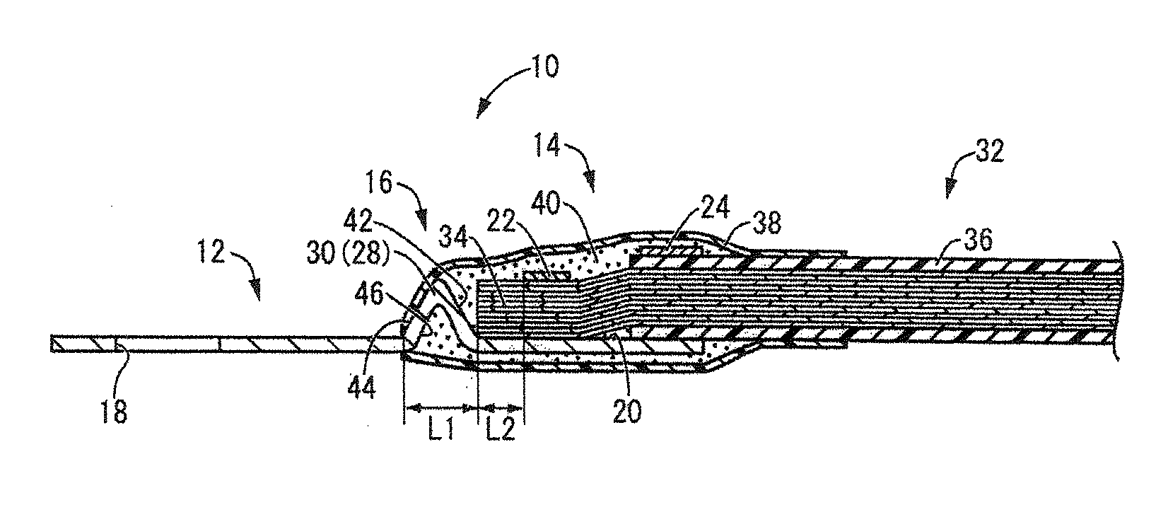
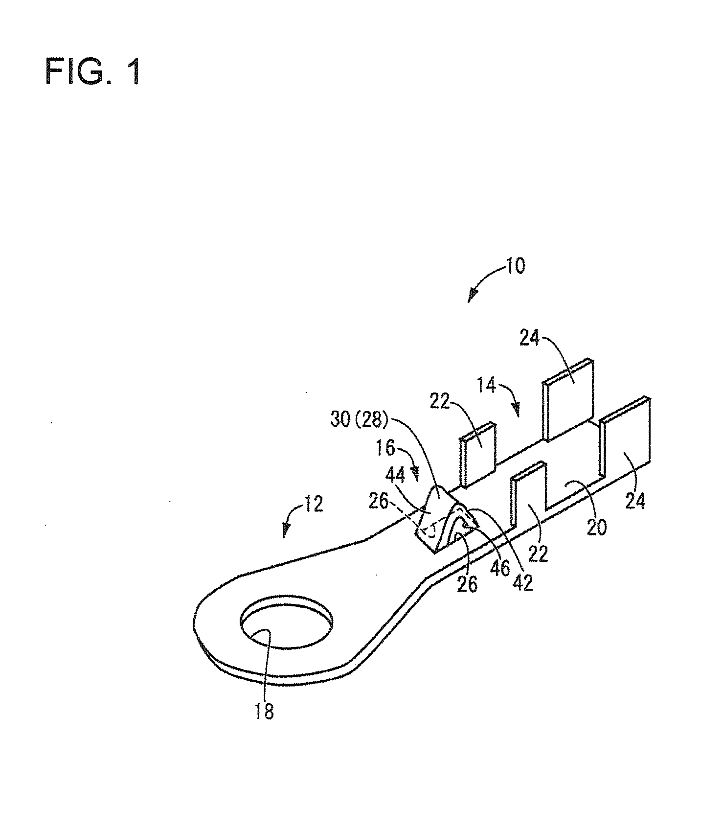
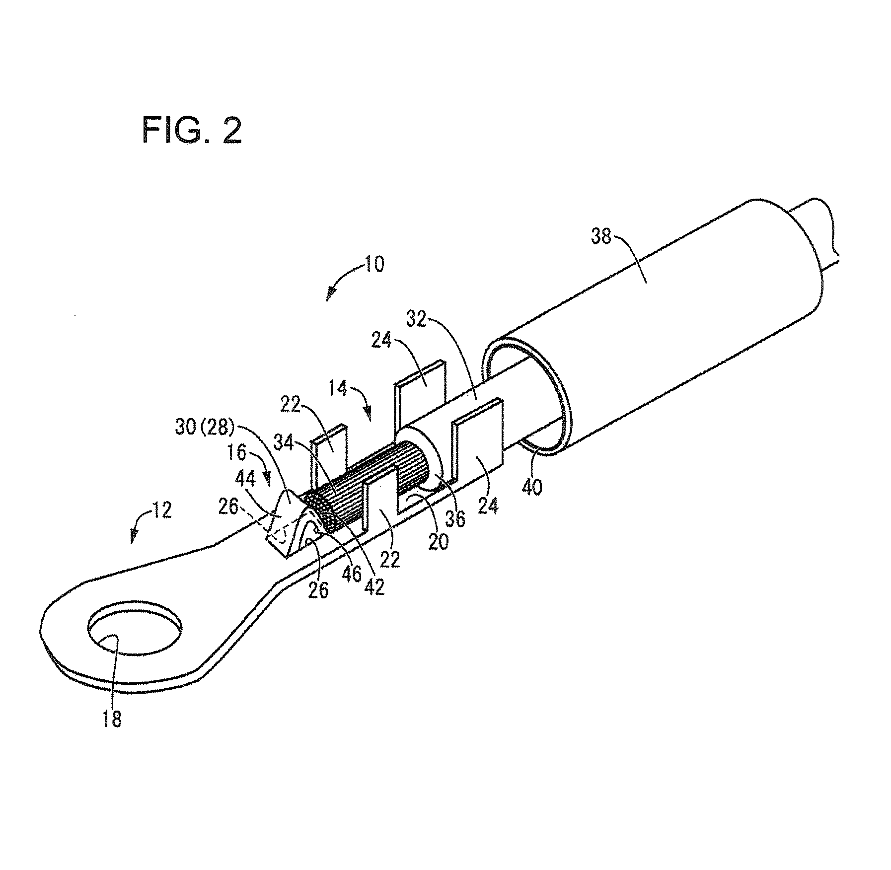
[0019]A crimp terminal 10 in accordance with an embodiment of the invention is identified by the numeral 10 in FIG. 1. The crimp terminal 10 is formed unitarily to include a connecting portion 12 that is connected conductively to an electrical connection target, a crimp portion 14 having core crimping portions 22 that are fixed by crimping to a core 34 of a coated wire 32, and a link 16 that extends therebetween.

[0020]The crimp terminal 10 has conductivity and is formed using various metal materials including brass, copper, copper alloy, aluminum and aluminum alloy, for example, capable of undergoing processing such as pressing and punching. In the present embodiment, the thickness dimension of the crimp terminal 10 is approximately constant throughout its entirety.

[0021]The plane of the connecting portion 12 has an approximately elliptical planer shape, and a through hole 18 passes through a central section thereof. The through hole 18 is utilized to insert a fastening bolt that is...


PUM


Abstract

A crimp terminal (10) has a connecting portion (12) that is conductively connected to an electrical connection target, a crimp portion (14) that has a core crimping portion (22) that is fixed by crimping to a core (38) of a coated wire (32), and a link (16) that extends between the connecting portion (12) and the crimp portion (14), a positioning protrusion (30) is formed by a pair of slits (26) penetrating through the link (16) and extending in a direction along which the link (16) so as to be separated from each other in a width direction orthogonal to the extension direction. An intermediate region (28) sandwiched between the slits (26) in the width direction is deformed to protrude on a side on which the core crimping portion (22) protrudes.

Description

BACKGROUND OF THE INVENTION[0001]1. Field of the Invention[0002]The invention relates to a crimp terminal that is attached by crimping to an exposed core at the end of a coated wire.[0003]2. Description of the Related Art[0004]Crimp terminals that are crimped to an exposed core at the end of a coated wire have been employed widely with coated wires that are used in the electrical systems of cars and the like. JP 5-31130A discloses such crimp terminals that have a connecting portion formed from a conductive member, such as a metal, and conductively connected to an electrical connection target, a crimp portion having a core crimping portion that is fixed by crimping to an outer peripheral surface of the core of the coated wire, and a link that extends therebetween. To ensure the waterproofness of the section of the crimp terminal attached to the coated wire, the crimp portion and the core are covered in a sealed state, by inserting a heat shrinkable tube containing hot-melt adhesive o...

Claims


Application Information

Patent Timeline
IPC IPC(8): H01R13/52
CPCH01R13/5216H01R4/185H01R4/70Y10S439/932H01R4/18H01R4/72H01R11/12
Inventor IIO, KIYOKAZU
Owner SUMITOMO WIRING SYST LTD
Why Eureka
Try Eureka