Electric heating catalyst
a technology of heating catalyst and heat exchanger, which is applied in the direction of physical/chemical process catalysts, machines/engines, mechanical equipment, etc., can solve the problems of reducing difficulty in rising temperature of this extraelectrode part, damage or breakage of heater elements, etc., so as to improve the purification rate of exhaust gas and suppress breakage or damage of heater elements
- Summary
- Abstract
- Description
- Claims
- Application Information
AI Technical Summary
Benefits of technology
Problems solved by technology
Method used
Image
Examples
first embodiment
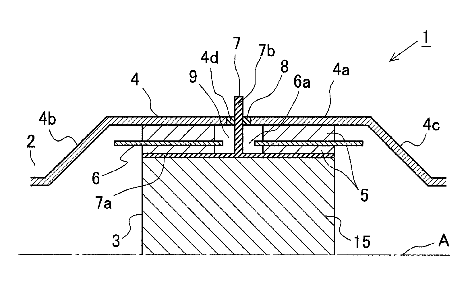
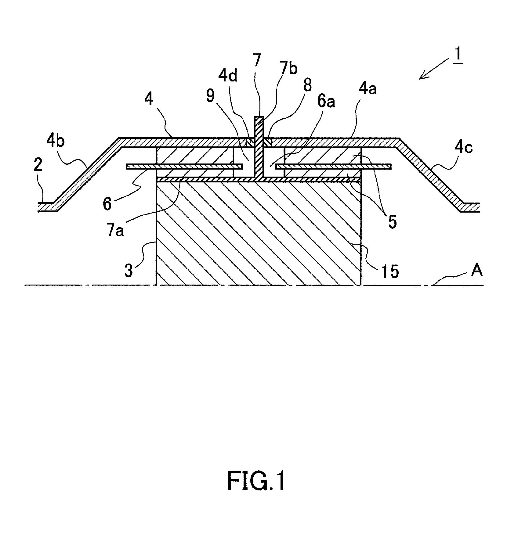
[0033]FIG. 1 is a view showing the schematic construction of an electric heating catalyst (EHC) according to this first embodiment of the present invention. The EHC 1 according to this embodiment is arranged in an exhaust pipe of an internal combustion engine mounted on a vehicle. The internal combustion engine may be a diesel engine, or may be a gasoline engine. In addition, the EHC 1 according to this embodiment can also be used in a vehicle which adopts a
[0034]FIG. 1 is a cross sectional view which shows the EHC 1 cut in a longitudinal direction thereof along a central axis A of the exhaust pipe 2 of the internal combustion engine. Here, note that the shape of the EHC 1 is in line symmetry with respect to the central axis A, and hence, in FIG. 1, only an upper part of the EHC 1 is shown for the sake of convenience.
[0035]The EHC 1 according to this embodiment is provided with a catalyst carrier 3, a casing 4, a mat 5, an inner pipe 6, and electrodes 7. The catalyst carrier 3 is fo...
first modification
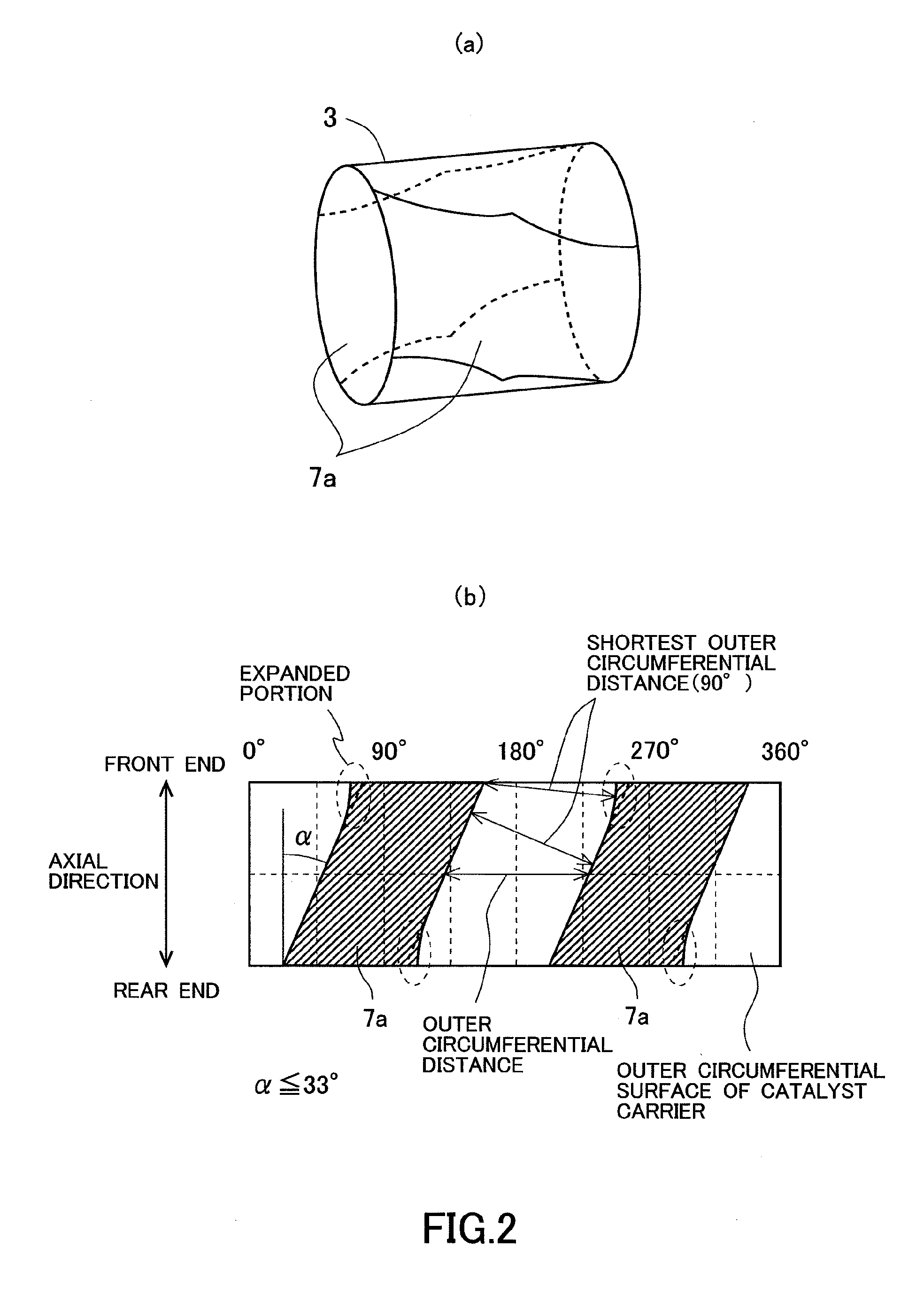
[0066]In the following, reference will be made to a first modification of this embodiment. FIG. 6 is a view showing the schematic construction of surface electrodes in an EHC according to this modification. FIG. 6(a) shows a perspective view of a catalyst carrier, and FIG. 6(b) is a view showing a state in which an outer circumferential surface of the catalyst carrier has been developed. In FIG. 6(b), diagonally shaded areas indicate portions in which the surface electrodes 7a are arranged.
[0067]In this modification, similarly as described above, the surface electrodes 7a each spirally extend from one end toward the other end of the catalyst carrier 3 along the outer circumferential surface of the catalyst carrier 3. In addition, the two surface electrodes 7a are formed in such a manner that they mutually cross each other with the catalyst carrier 3 being sandwiched therebetween. Then, in this embodiment, as shown in FIG. 6, the width of each surface electrode 7a in the vicinity of ...
second modification
[0072]In the following, reference will be made to a second modification of this embodiment. As in the above-mentioned embodiment and the first modification, if the width of each surface electrode 7a in a portion(s) thereof in the direction parallel to the circumferences of the end faces of a catalyst carrier 3 is enlarged, in the portion(s) which is enlarged in width, a rectilinear distance between the surface electrodes becomes smaller in comparison with those portions which are not enlarged in width. Here, note that the rectilinear distance between the surface electrodes is the length of a straight line when the side ends of both the surface electrodes 7a are connected with each other by the straight line which passes through the inside of the catalyst carrier 3 and is orthogonal to the axial direction of the catalyst carrier 3.
[0073]A part with a large rectilinear distance between the surface electrodes, tends to allow, upon electrical energization thereof, electric current to fl...
PUM
| Property | Measurement | Unit |
|---|---|---|
| spiral angle | aaaaa | aaaaa |
| central angle | aaaaa | aaaaa |
| spiral angle | aaaaa | aaaaa |
Abstract
Description
Claims
Application Information
 - R&D
- Intellectual Property
- Life Sciences
- Materials
- Tech Scout
- Unparalleled Data Quality
- Higher Quality Content
- 60% Fewer Hallucinations
Browse by: Latest US Patents, China's latest patents, Technical Efficacy Thesaurus, Application Domain, Technology Topic, Popular Technical Reports.
© 2025 PatSnap. All rights reserved.Legal|Privacy policy|Modern Slavery Act Transparency Statement|Sitemap|About US| Contact US: help@patsnap.com


